Nozzle for plasma torch

a plasma torch and nozzle technology, applied in the direction of manufacturing tools, soldering devices, auxillary welding devices, etc., can solve the problems of insufficient cooling, high cutting speed, and large cutting width, and achieve the effect of sufficient cooling of the nozzle and easy formation

Inactive Publication Date: 2005-04-21
KOIKE SANSO KOGYO CO LTD
View PDF8 Cites 70 Cited by
  • Summary
  • Abstract
  • Description
  • Claims
  • Application Information

AI Technical Summary

Benefits of technology

[0013] In the nozzle for the plasma torch, the cooling water supplied through the cooling water supplying passage is introduced to the annular water passage through the connecting water passage, so as to sufficiently cool the surroundings of the injection port for the plasma arc in the nozzle, and thereafter, is drained through the cooling water draining pipe through the other connecting water passage. That is to say, the cooling water can form a flow from the supplying passage to the draining passage by the use of the connecting water passages and the annular water passage, thus sufficiently cooling the nozzle.
[0014] Furthermore, the plurality of connecting water passages are arranged over the entire circumference of the nozzle, and the circumferential surface of the nozzle can be cooled with the cooling water flowing in the connecting water passages by connecting the water supplying pipe and the wate

Problems solved by technology

The plasma cutting has raised a problem of a cutting width greater than that by the gas cutting, although the cutting speed is high in the plasma cutting.
Therefore, there ha

Method used


Image

  • Nozzle for plasma torch
  • Nozzle for plasma torch
  • Nozzle for plasma torch

Examples


embodiment 1

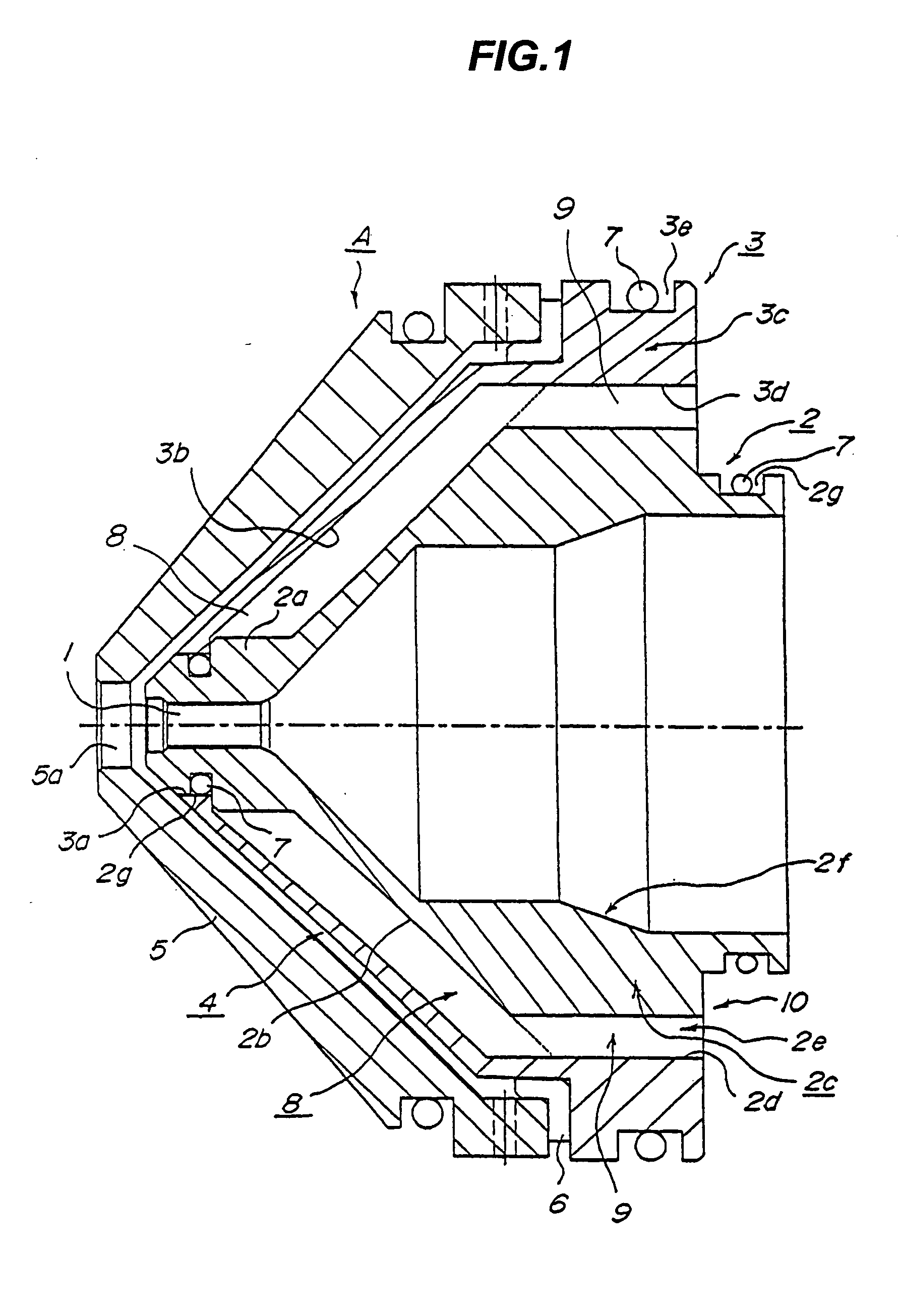
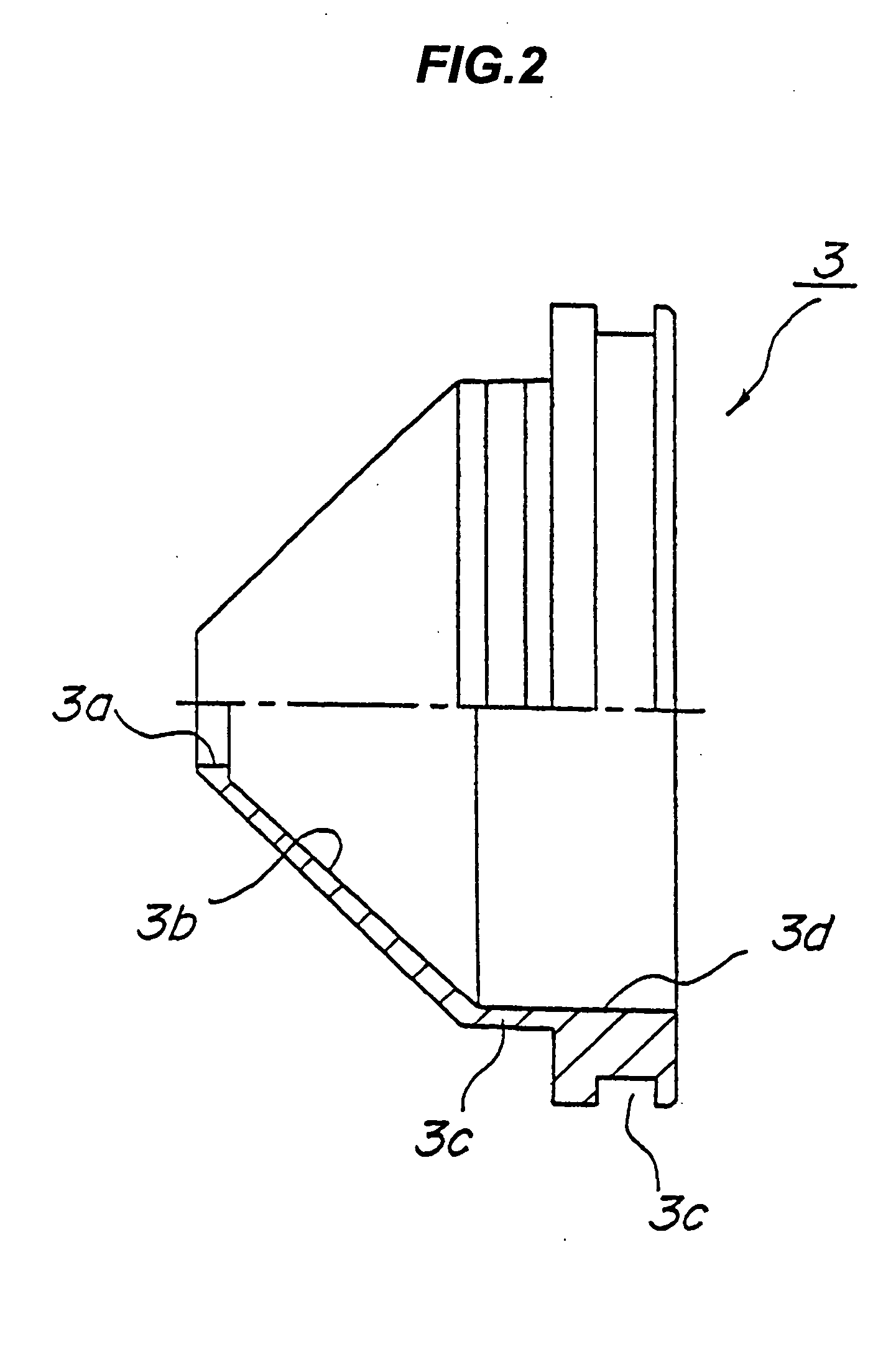
[0039] Next, a description will be given below of a nozzle in a preferred embodiment according to the present invention in reference to the attached drawings. FIG. 1 is a cross-sectional view showing the configuration of a nozzle which can inject a secondary air flow in association with a plasma arc; FIG. 2 is a cross-sectional view showing the shape of an outer nozzle; FIG. 3 is a cross-sectional view showing the shape of an inner nozzle; FIG. 4 is a cross-sectional view showing the configuration of a plasma torch; and FIG. 5 is a cross-sectional view showing essential parts of the plasma torch in enlargement.

[0040] Prior to the description of a nozzle A in the present embodiment, explanation will be simply made below on the configuration of a plasma torch B in reference to FIGS. 4 and 5. The plasma torch B shown in FIGS. 4 and 5 is constituted of mainly a passage for cooling water to be supplied to an electrode 11 and the nozzle A.

[0041] The plasma torch B is configured such tha...

embodiment 2

[0065] Next, an inner nozzle in a second embodiment will be explained in reference to FIG. 6. Incidentally, the same component parts and the component parts having the same functions as those in the first embodiment are designated by the same reference numerals, and therefore, the explanation will be omitted.

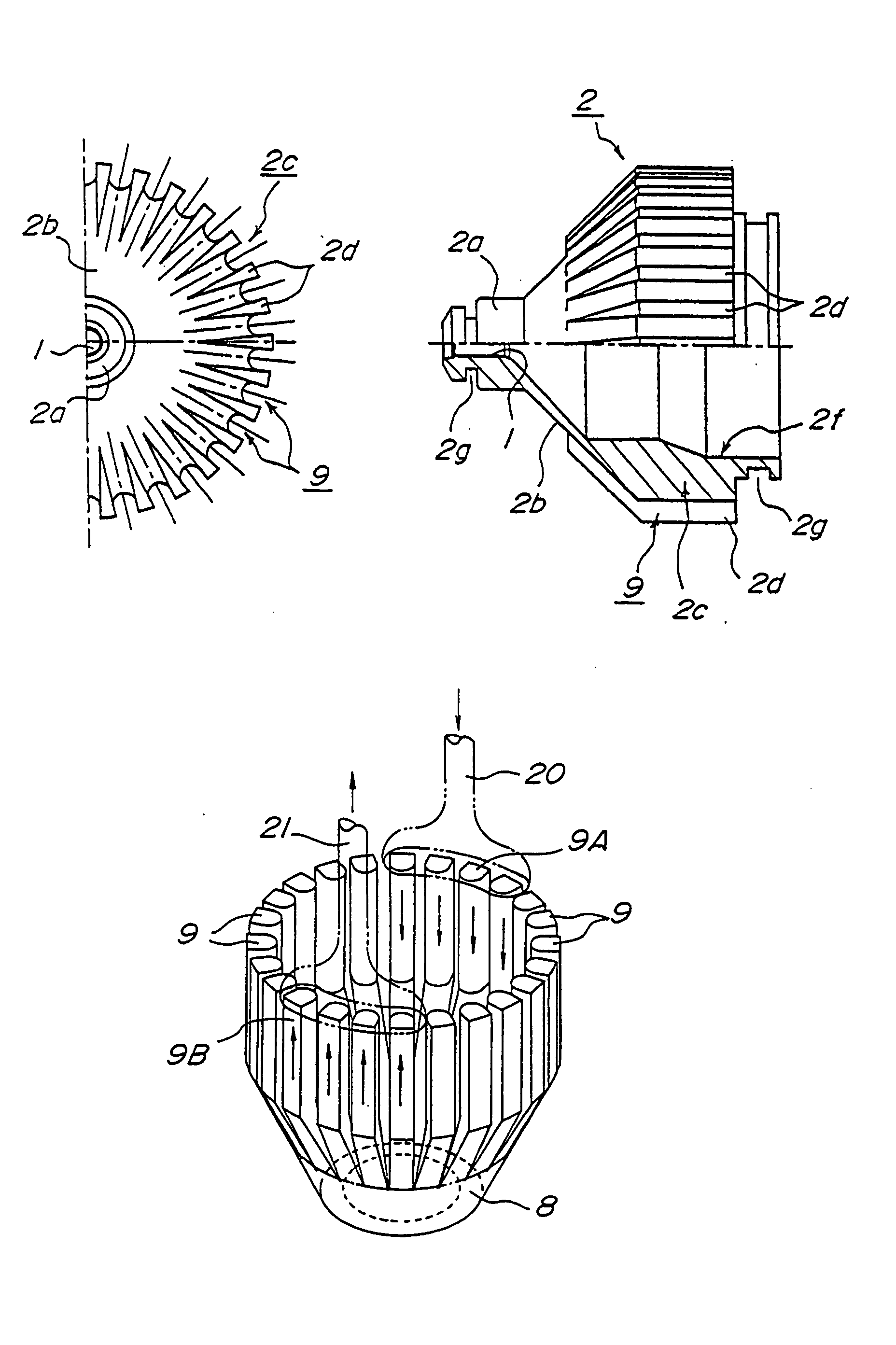
[0066] As shown in FIGS. 6A and 6B, an inner nozzle 2 includes numerous dividing pieces 2d formed from a tapered portion 2b (i.e., a tapered surface 2b) to a base 2c. Independent water passages 9 in the same number as that of dividing pieces 2d are formed by fitting the inner nozzle 2 to an outer nozzle 3. In the inner nozzle 2 in the present embodiment, the dividing pieces 2d extend toward the tapered surface 2b, so that the independent connecting water passage 9 becomes long, thereby more securely cooling a wall 2a.

[0067] Furthermore, FIG. 6C is a perspective view showing an annular water passage 8, the connecting water passages 9, a water supplying passage 20 and a water dr...


PUM

PropertyMeasurementUnit
Circumferenceaaaaaaaaaa

Abstract

The present invention relates to a nozzle for a plasma torch, in which the nozzle is detachably attached to the plasma torch and has an injection port for injecting a plasma arc formed at the center thereof, the nozzle for a plasma torch comprising: a water supplying pipe for cooling water; a water draining pipe for the cooling water; an annular water passage arranged around the injection port; and a plurality of connecting water passages for independently connecting the water supplying pipe to the annular water passage and the water draining pipe to the annular water passage.

Description

BACKGROUND OF THE INVENTION [0001] 1. Field of the Invention [0002] The present invention relates to a nozzle for a plasma torch and, more particularly, to a cutting nozzle for injecting a plasma arc toward a workpiece to be cut for the purpose of cutting, in which so-called high quality cutting can be achieved at a narrow cutting width with enhanced cutting performance. [0003] 2. Description of the Related Art [0004] In the case where a workpiece to be cut such as a steel plate or a stainless steel plate is cut, there has been frequently adopted a plasma cutting method capable of cutting at an increased cutting speed in comparison with a gas cutting method. In the plasma cutting method, a plasma arc is injected toward a workpiece to be cut, thereby fusing a base material by heat of the plasma arc and cutting the workpiece to be cut while removing the fused material by the injection energy of the plasma arc. [0005] The configuration of a plasma torch disclosed in Japanese Patent App...

Claims


Application Information

Patent Timeline
IPC IPC(8): B23K10/00H05H1/28H05H1/34
CPCH05H1/28H05H2001/3457H05H1/34H05H1/3457H05H1/3423B23K10/02B23K37/003
Inventor KOIKE, TETSUOFURUJO, AKIRAKATO, YOSHIYUKI
Owner KOIKE SANSO KOGYO CO LTD
Why Eureka
Try Eureka