Direction sensitive detector of radiation

a detector and direction technology, applied in the direction of x/gamma/cosmic radiation measurement, radiation particle tracking, instruments, etc., can solve the problems of large apparatus size, heavy weight, and inability to measure the incident direction of radiation incident from afar, and achieve the effect of light weight, simple shape and low cos

Inactive Publication Date: 2005-04-21
JAPAN ATOMIC ENERGY AGENCY INDEPENDANT ADMINISTRATIVE CORP
View PDF2 Cites 34 Cited by
  • Summary
  • Abstract
  • Description
  • Claims
  • Application Information

AI Technical Summary

Benefits of technology

[0008] Since the detector of the present invention is provided with a structure having the radiation detection system in which, on the outer periphery of a scintillating optical fiber arranged in a state of being curved in a circular arc shape, a large number of flat collimators are arranged in a radial pattern at nearly even intervals, the incident direction measurement can be carried out even for radiations incident in parallel. Additionally, the collimators are simple in shape and can be made light in weight, the number of the necessary collimators is relatively small, the number of the necessary meas

Problems solved by technology

The problems to be solved by the present invention include a problem such that the incident direction of a radiation inc

Method used


Image

  • Direction sensitive detector of radiation
  • Direction sensitive detector of radiation
  • Direction sensitive detector of radiation

Examples


Embodiment Construction

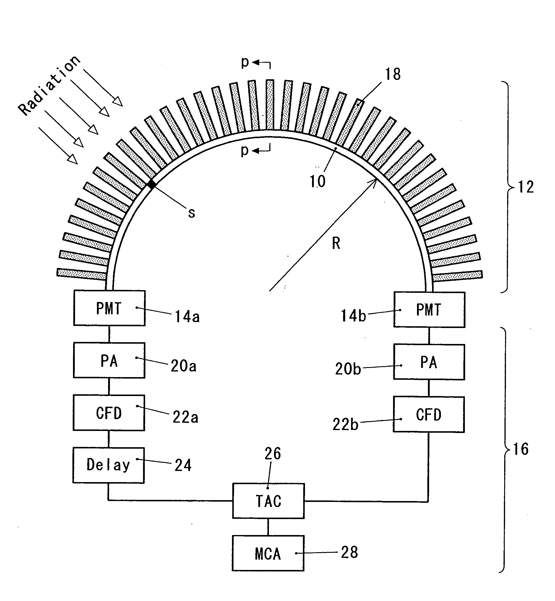
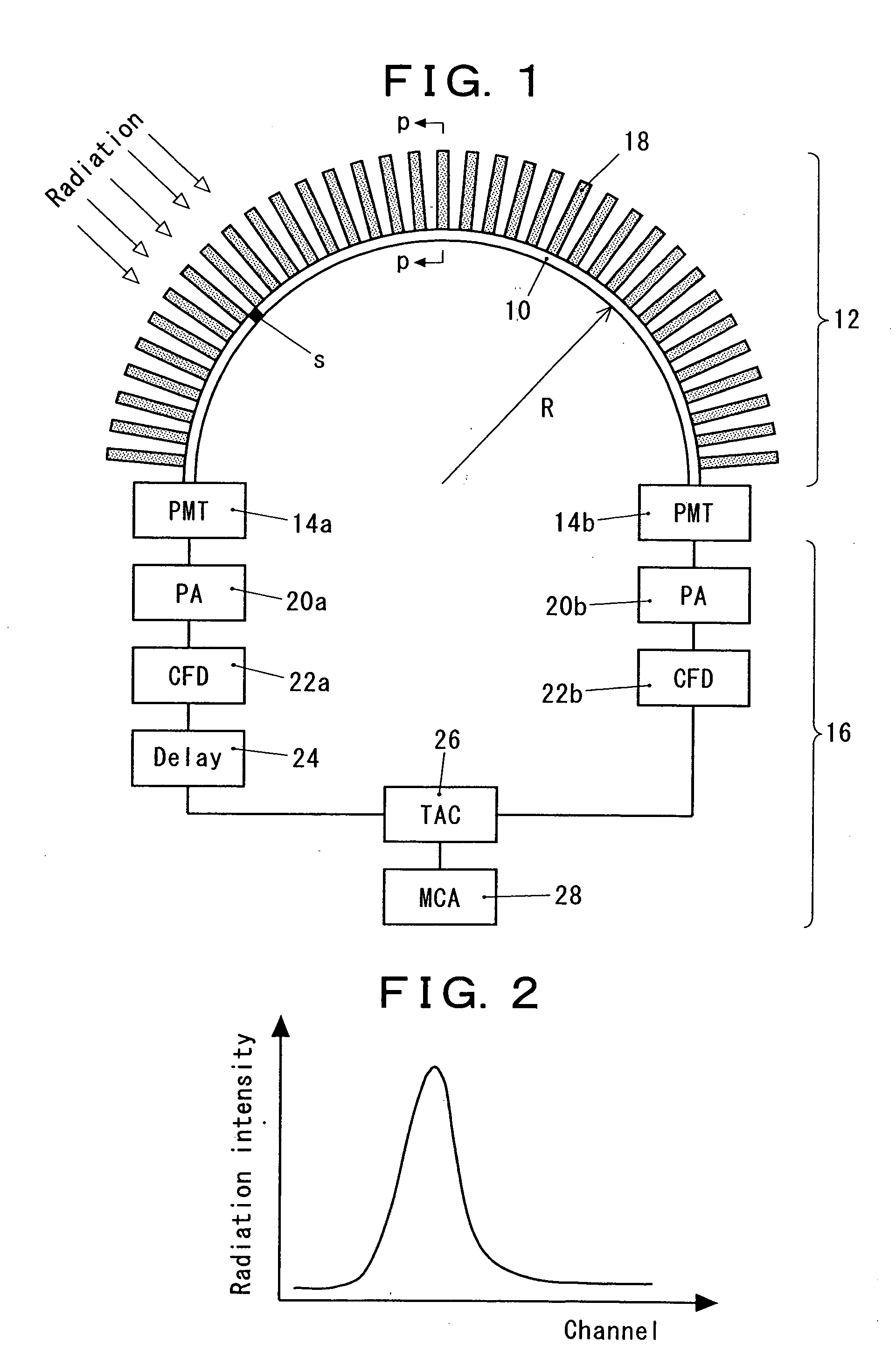
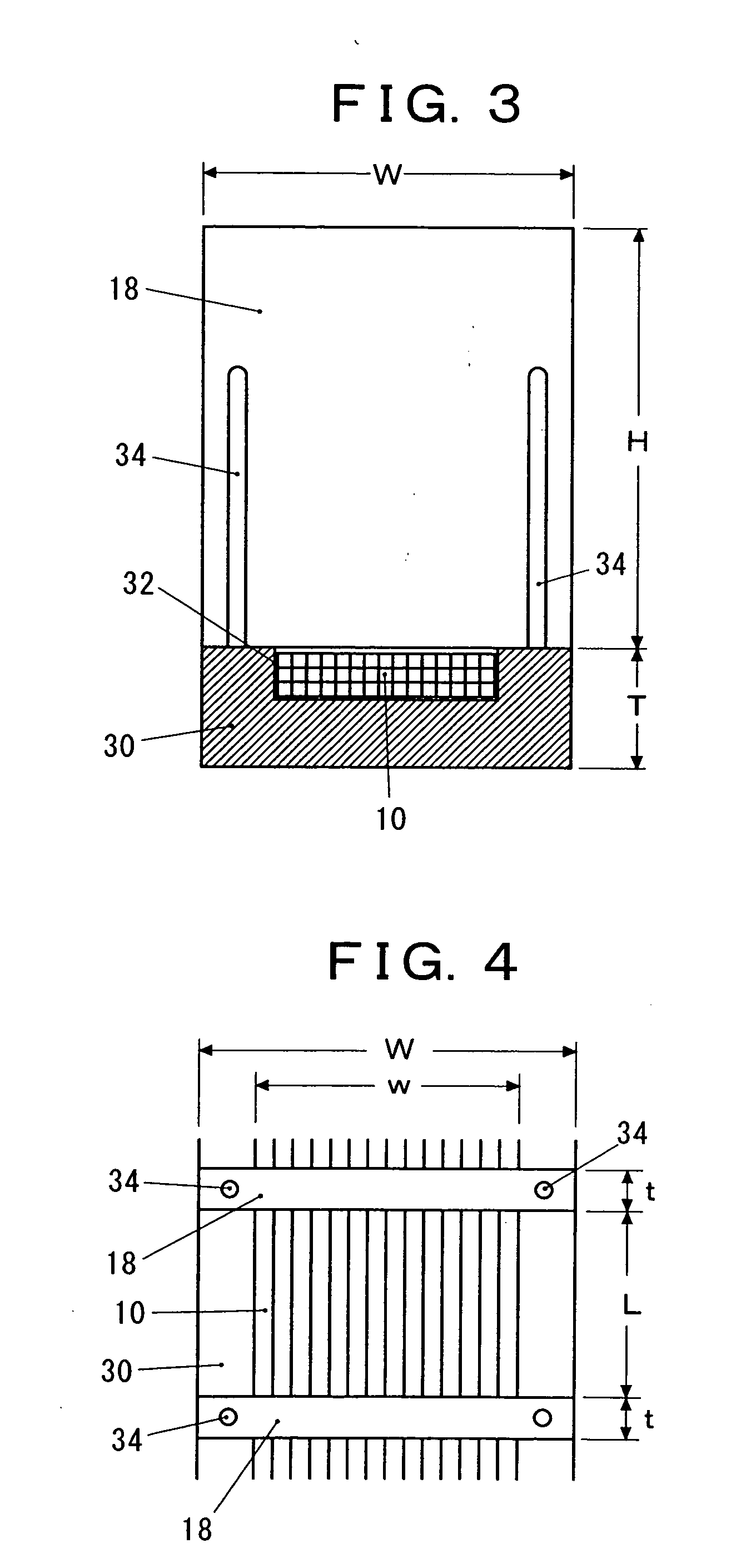
[0016] In the radiation detection system of the present invention, at least one scintillating optical fiber is arranged in a state of being curved in a circular arc shape, and on the outer periphery of the fiber, a large number of flat collimators are arranged in a radial pattern at nearly even intervals. Only the radiation which passes through any of the gaps between the adjacent collimators can reach the scintillating optical fiber to be converted into a light signal. The incident position of the radiation on the scintillating optical fiber is derived from the arrival time difference between the electric signals from the two light receiving elements, and thus the incident direction of the radiation is detected. By providing a constitution in which two sets, each including a scintillating optical fiber and a large number of flat collimators, are arranged so as to cross each other at right angles at the centers thereof, the radiations from almost all the directions can be detected. ...


PUM


Abstract

An apparatus which is capable of detecting the incident direction of a radiation incident from afar and which is made to be small in size and light in weight is provided. The apparatus comprises a radiation detection system 12 having a scintillating optical fiber 10 converting an incident radiation into a light signal, light receiving elements 14a, 14b respectively connected to both ends of said scintillating optical fiber and converting the light signals propagating in two directions along said scintillating optical fiber into electric signals, and a radiation analysis system 16 deriving the incident position of the radiation on the basis of the difference between the arrival times of the electric signals from said light receiving elements. The scintillating optical fiber is arranged in a state of being curved in a circular arc shape, and a large number of flat collimators 18 are arranged on the outer periphery of the scintillating optical fiber in a radial pattern at nearly even intervals.

Description

FIELD OF THE INVENTION [0001] The present invention relates to a direction sensitive detector of a radiation incident from afar, more specifically, an apparatus for detecting the incident direction of a radiation having a structure in which a scintillating optical. fiber is arranged in a state of being curved in a circular arc shape and a large number of flat collimators are arranged on the outer periphery of the scintillating optical fiber in a radial pattern at nearly even intervals. This technique is useful for such cases including the direction sensitive measurement of a radiation or the determination of a position of a radiation source for radioactivity emitted in a nuclear accident and the like. BACKGROUND OF THE INVENTION [0002] As an available technique for measuring radiation distribution, there is a radiation detection apparatus which includes a radiation detection system having a scintillating optical fiber converting an incident radiation to a light signal; light receivi...

Claims


Application Information

Patent Timeline
IPC IPC(8): G01T1/29G01T1/00G01T1/20G01T5/08G01T7/00H01L31/09
CPCG01T1/201
Inventor TORII, TATSUO
Owner JAPAN ATOMIC ENERGY AGENCY INDEPENDANT ADMINISTRATIVE CORP
Why Eureka
Try Eureka