
Inline stacker with non-interrupt gap generator and integrated drive control and jam response

a gap generator and stacker technology, applied in the direction of thin material processing, article delivery, transportation and packaging, etc., can solve the problems of insufficient reliability of encoder signal, increased jamming, and easy jamming of encoder signal

Inactive Publication Date: 2005-04-21
JET GRAPHICS
View PDF12 Cites 7 Cited by
  • Summary
  • Abstract
  • Description
  • Claims
  • Application Information

AI Technical Summary

Benefits of technology

[0011] Continuous rotation of the ball screw also changes the lateral dimension of the collection well to accommodate products of different width. One positive control is an idler wheel mounted over the collection well that deflects products leaving the gap generator to the collection well without overshoot.

Problems solved by technology

A plate or nip roll interrupts the shingled steam carried on a fixed upstream conveyor while an adjacent, fixed, downstream conveyor carries a downstream set of the shingled goods, thus creating a gap.
In practice, however, additional wiring at each location is necessary, the encoder signal has proven to be not sufficiently reliable, and this control is insensitive to downstream problems of the stacker such as a paper jam.
Further, jams are facilitated by interruptions in a continuously moving shingled stream.
This “fat” leading end of the stream, once released by lifting the interrupting finger or nip roll, is more susceptible to jamming than a stream of uniform height.
Jams in known machines are often difficult and time-consuming to clear.
There is further time and product lost on restart.

Method used


Image

  • Inline stacker with non-interrupt gap generator and integrated drive control and jam response
  • Inline stacker with non-interrupt gap generator and integrated drive control and jam response
  • Inline stacker with non-interrupt gap generator and integrated drive control and jam response

Examples


Embodiment Construction

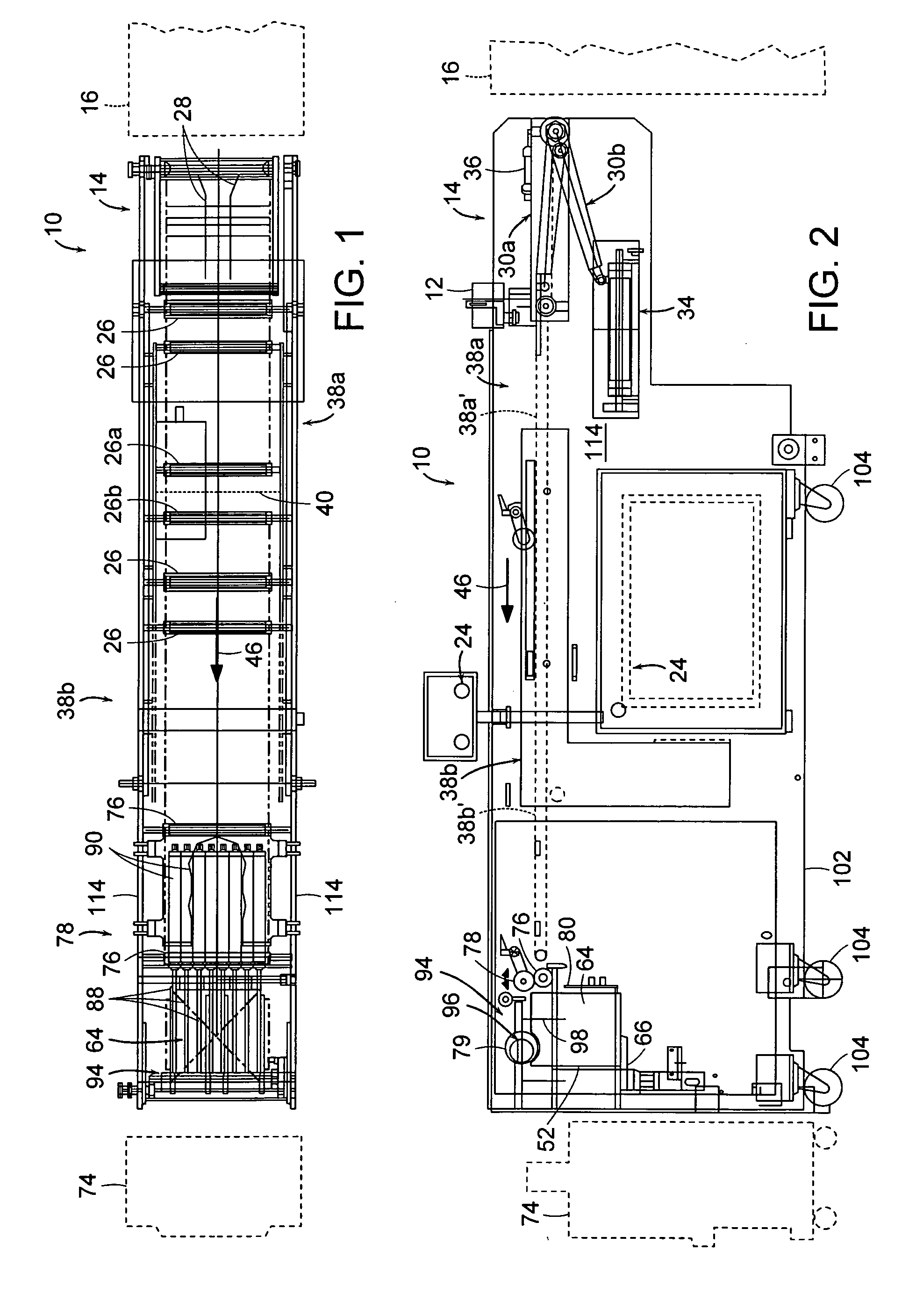
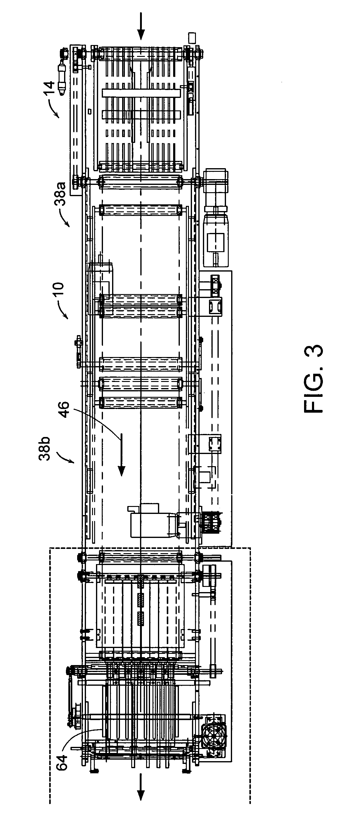
[0034] With reference to FIGS. 1-16, the stacker 10 of the present invention has various features that alone, or in combination, solve various problems, such as those discussed above, that have plagued the known stackers. A principal feature is that the control of the stacker speed and stacking operations originates with a sheet counter 12 located at a stacker infeed section 14. The counter 12 sets the speed of the stacker to match the output of the equipment 16 which feeds the stacker. For the purposes of this description, this in-line equipment operating a succession of flat sheet products to be stacked will be described as a printing press and the products as printed paper sheets, including folder sheets such as signatures. The counter 12 also controls the operation of a gap generator 18 of the stacker 10 to produce a gap in an infeed shingled stream 20 of products 22. The gap in the shingled stream is created after a predetermined number of the products has been detected by the ...


PUM


Abstract

An inline stacker receives a shingled stream of printed sheet products from a printing press, or finishing equipment, at line speed. A sheet counter at an infeed conveyor section controls the operation of the inline stacker. The infeed conveyor can pivot to a divert position where it feeds the stream to a bi-directional conveyor. A following gap generator section of the stacker has two conveyors with opposed movable ends that are physically separated in the conveying direction by a small gap. The infeed conveyor and gap generator conveyor sections carry the stream at a substantially constant speed, which can be the line speed. To produce a gap in the shingled stream that defines a bundle size, the movable conveyor ends defining the gap between the conveyor gap generator sections move downstream in unison at the speed of the upstream conveyor. At the same time, the speed of the downstream conveyor is briefly increased. The movable ends and the increased conveyor speed then return to their initial status. Stacks of a predetermined size are collected on a forked elevator with mirror movement side walls and other product movement and position controls. Ball-screw-driven and cam-driven side joggers (at the infeed) align the stack and infeed stream laterally. The ball screw jogger, under control of a central controller and an associated servo motor rotates continuously in one direction to open the side walls in response to a sensed jam. The stacker is portable and mechanized for side lay adjustment to align with the press or finishing equipment.

Description

CROSS-REFERENCE TO RELATED APPLICATION [0001] This application claims priority under §35 USC 119 of prior U.S. provisional application Ser. No. 60 / 476,498 filed Jun. 5, 2003, the disclosure of which is incorporated herein by reference.BACKGROUND OF THE INVENTION [0002] This invention relates in general to apparatus and methods for forming stacks of sheet materials. More specifically, it relates to an in-line stacker that receives a shingled stream of printed sheets, e.g. from a printing press, and / or in-line or off-line finishing equipment, and reliably forms them into a series of stacks of a predetermined number at press speed. [0003] In many applications, it is desired to form a shingled stream of sheet products into a succession of bundles each containing a known number of sheet or folded pieces. A major application is the stacking and bundling of printed material as it leaves a printing press, and / or in-line or off-line finishing equipment such as rotary cutters, folders, perfor...

Claims


Application Information

Patent Timeline
Patent Type & Authority Applications(United States)
IPC IPC(8): B65H33/12
CPCB65H29/66B65H33/12B65H2511/30B65H2513/50B65H2220/01B65H2220/02B65H2701/176
Inventor WILLIAMS, ROBERT M.COGSWELL, JOHNBERNASCONI, MATTHEWMEEHAN, ROBERT
Owner JET GRAPHICS
Learn More