
Image taking apparatus

a technology of image taking and apparatus, applied in the field of image taking apparatus, can solve the problems of reducing an optical performance, reducing unable to avoid the decrease of an optical performance, so as to reduce the number of parts and cost, simplify the insertion and removal mechanism, and relax the affection of an optical performance

Inactive Publication Date: 2005-04-21
SONY CORP
View PDF11 Cites 25 Cited by
  • Summary
  • Abstract
  • Description
  • Claims
  • Application Information

AI Technical Summary

Benefits of technology

[0027] In the present invention in order to solve the above mentioned problems, there is proposed a mechanism which is able to locate a filter made of film material or sheet material by freely inserting / removing on an optical axis of an image taking optical system.
[0033] Further, in an adaptation to an imaging system having an inner focus type configuration, it becomes not necessary to use the above mentioned methods (a) to (c), and this invention is effective in downsizing of a lens tube and in preventing deterioration of an optical performance.

Problems solved by technology

However, according to the conventional configuration, there are problems in a structure of the insertion and removal mechanism for the IR cut filter, in the number of parts, and in its cost.
Further when compared with an image taking apparatus not having the above mentioned night shot function, this causes a high cost, and also causes extreme disadvantages in an aspect of assembly process.
Further regarding problem that an image focus location is changed due to the thickness of the IR cut filter when the filter is inserted / removed, it becomes necessary to prepare additional parts such as a dummy glass and spacer in case of the above mentioned methods (a), and (b).
Further in case of the above mentioned method (c), it is necessary to increase a move amount of a focus lens corresponding to the correction, and accordingly this prevents downsizing of a lens tube, and also a decrease of an optical performance cannot be avoided.

Method used


Image

  • Image taking apparatus
  • Image taking apparatus
  • Image taking apparatus

Examples


Embodiment Construction

[0044] This invention is to propose an image taking apparatus having a mechanism for freely inserting / removing a filter between a lens or lens group and an imaging surface, and any affection to optical performances caused by a simplification of the mechanism and the insertion / removal of the filter is relaxed.

[0045] In place of a conventional glass IR cut filter, film materials or sheet materials are used to form an IR cut filter, and the IR cut filter is directly driven without using any decelerator, and a support frame. Thereby, it is able to perform downsizing of an optical system and the filter drive mechanism, reduction of the number of parts, and elimination of influence of the insertion / removal of the filter to the image focus location by using such thin IR cut filter. Accordingly, an image taking apparatus having a night shot mechanism is realized with a fully guaranteed optical performance.

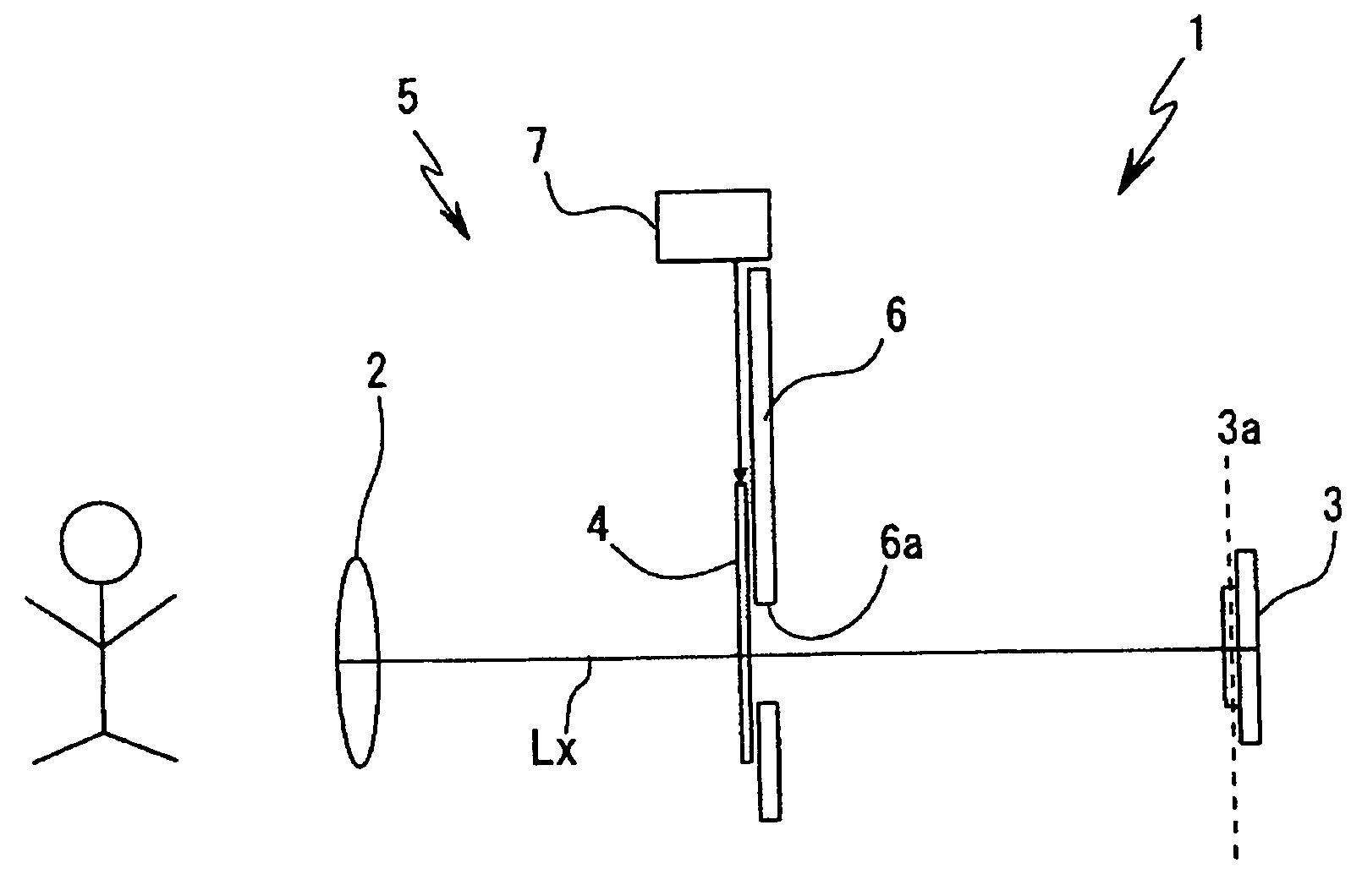
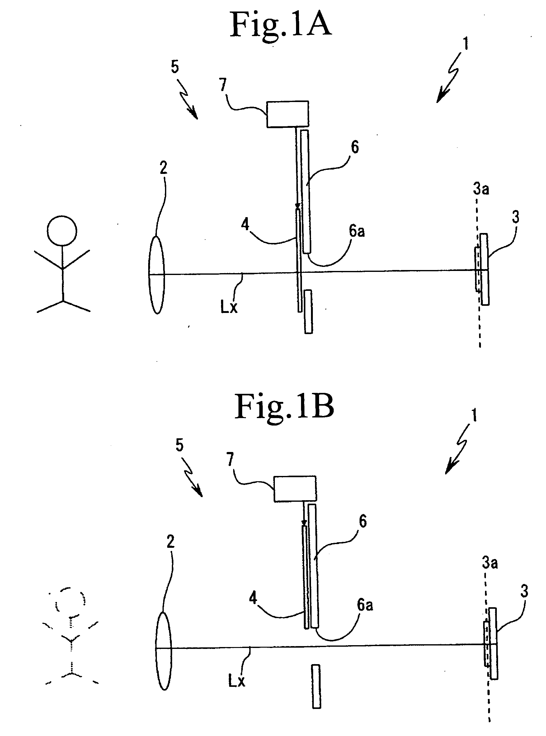
[0046]FIGS. 1A and 1B are schematic diagram for describing a basic configuration of ...


PUM


Abstract

In an image taking apparatus having a mechanism for freely inserting / removing an IR cut filter on an optical axis of an image taking optical system of the image taking apparatus, the IR cut filter is made of one of film material and sheet material. Further the mechanism changes an image taking mode of the image taking apparatus between a first mode where the IR cut filter is located on the optical axis of the image taking optical system and a second mode, that is a low level light image taking mode where the IR cut filter is removed from the optical axis of the image taking optical system.

Description

BACKGROUND OF THE INVENTION [0001] 1. Field of the Invention [0002] This invention relates to a technology where an insertion and removal mechanism of a filter (IR cut filter and the like) is realized with less component parts than a conventional technology, and when an image taking apparatus using this mechanism is applied to an image taking apparatus such as a video camera, a digital still camera, and the like, it becomes possible to perform downsizing and low cost of the image taking apparatus. [0003] 2. Description of the Related Art[0004] An image taking apparatus having a mechanism capable of inserting an IR cut filter on an optical path of a lens system depending on a level of a luminance signal is well known, wherein such mechanism is able to selectively change between a low level light image taking mode (hereinafter referred to as a night shot function) and a normal image taking mode. [0005] For example, in case of an apparatus provide with such mechanism that selectively i...

Claims


Application Information

Patent Timeline
IPC IPC(8): G03B7/18G03B11/00H04N5/225H04N5/238H04N101/00
CPCH04N5/2254H04N23/55
Inventor TSUTSUMI, TAKUYA
Owner SONY CORP
Learn More