Lens barrel and imaging apparatus

a technology of imaging apparatus and lens barrel, which is applied in the association of printed circuit non-printed electric components, instruments, television systems, etc., can solve the problems of limiting the use of flexible printed circuit boards, occupying space by two members, and affecting the miniaturization of imaging elements, so as to achieve the effect of reducing siz

Inactive Publication Date: 2005-04-21
SONY CORP
View PDF4 Cites 28 Cited by
  • Summary
  • Abstract
  • Description
  • Claims
  • Application Information

AI Technical Summary

Benefits of technology

[0013] According to the preferred embodiments of the present invention, the metal plate is mounted on the rear face of the part of the flexible printed circuit board on which the imaging element is mounted. As result, although the package of the imaging element and the part of the flexible printed circuit board which constitutes the imaging-element mounting section are reduced to considerably reduced sizes, the part of the flexible printed circuit board which constitutes the imaging-element mounting section does not undergo deformation even if the part of the flexible printed circuit board is heated during soldering between the first connecting terminals and the second connecting terminals, whereby the first connecting terminals and the second connecting terminals can be reliably soldered to one another and the imaging element and an image processing unit can be reliably interconnected. Accordingly, the present invention is also advantageous in terms of miniaturization.

Problems solved by technology

However, in a related art type of lens barrel, two members such as a hard printed circuit board and a flexible printed circuit board are needed as wiring members for interconnecting an imaging element and an imaging circuit, and if the imaging element is to be miniaturized with the miniaturization of lens barrels and imaging apparatuses, there is the disadvantage that the two members occupy a space and hinder the miniaturization of the imaging element.
There is a method of directly soldering an imaging element to a flexible printed circuit board without using a hard printed circuit board, but if the flexible printed circuit board itself is to be miniaturized with the miniaturization of lens barrels and imaging apparatuses, there occurs the disadvantage that the flexible printed circuit board cannot provide reliable interconnection between the imaging element and an imaging circuit, because the flexible printed circuit board has the nature that when the area of the flexible printed circuit board is small, the deformation thereof is promoted by heat applied to the flexible printed circuit board during soldering.

Method used


Image

  • Lens barrel and imaging apparatus
  • Lens barrel and imaging apparatus
  • Lens barrel and imaging apparatus

Examples


embodiment 1

EXAMPLE OF PREFERRED EMBODIMENT 1

[0043] An example of preferred embodiment 1 of the present invention will be described below with reference to the accompanying drawings.

[0044] In the present example of preferred embodiment, reference will be made to a case where a lens barrel according to the present invention is incorporated in an imaging apparatus.

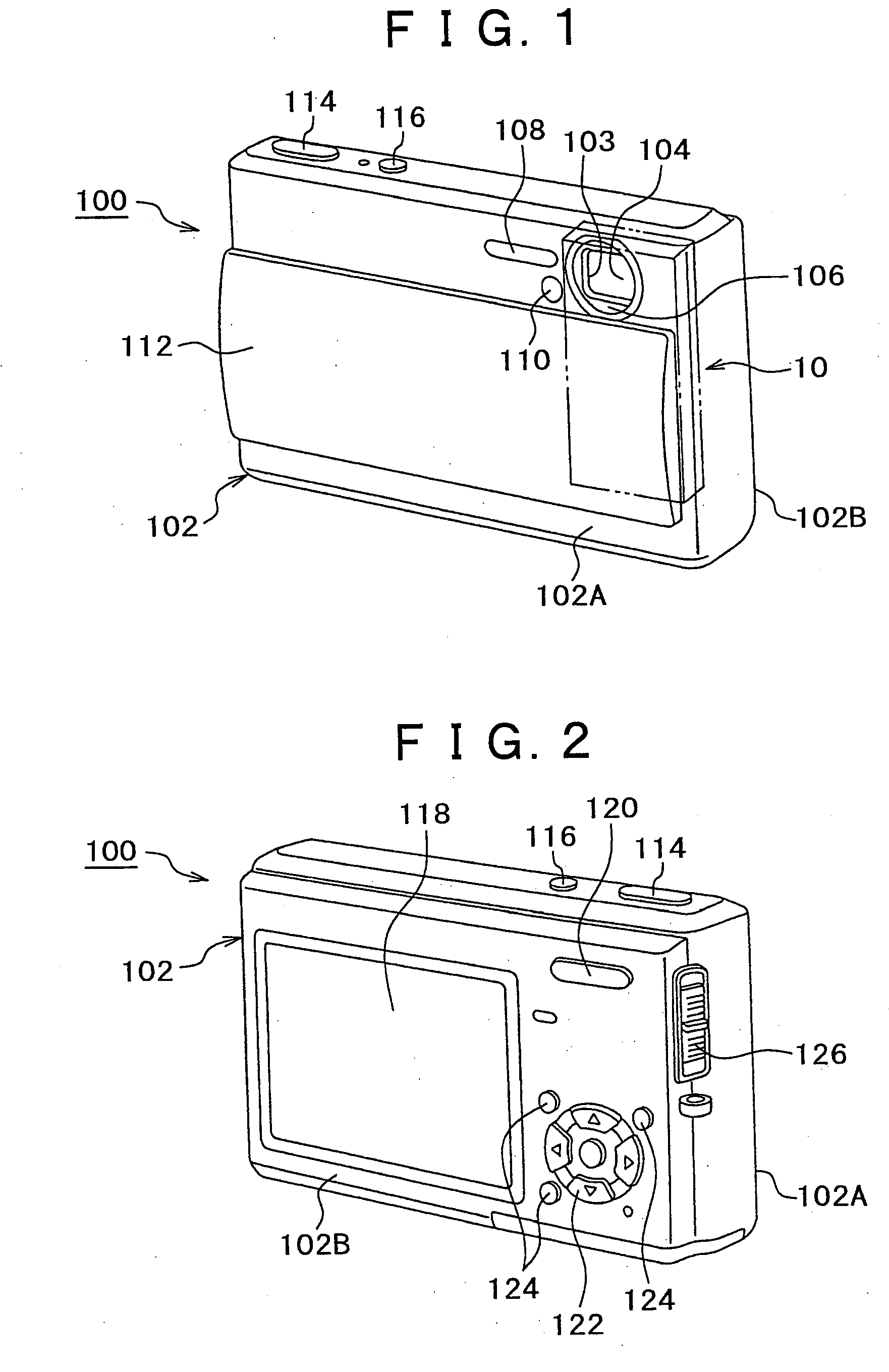
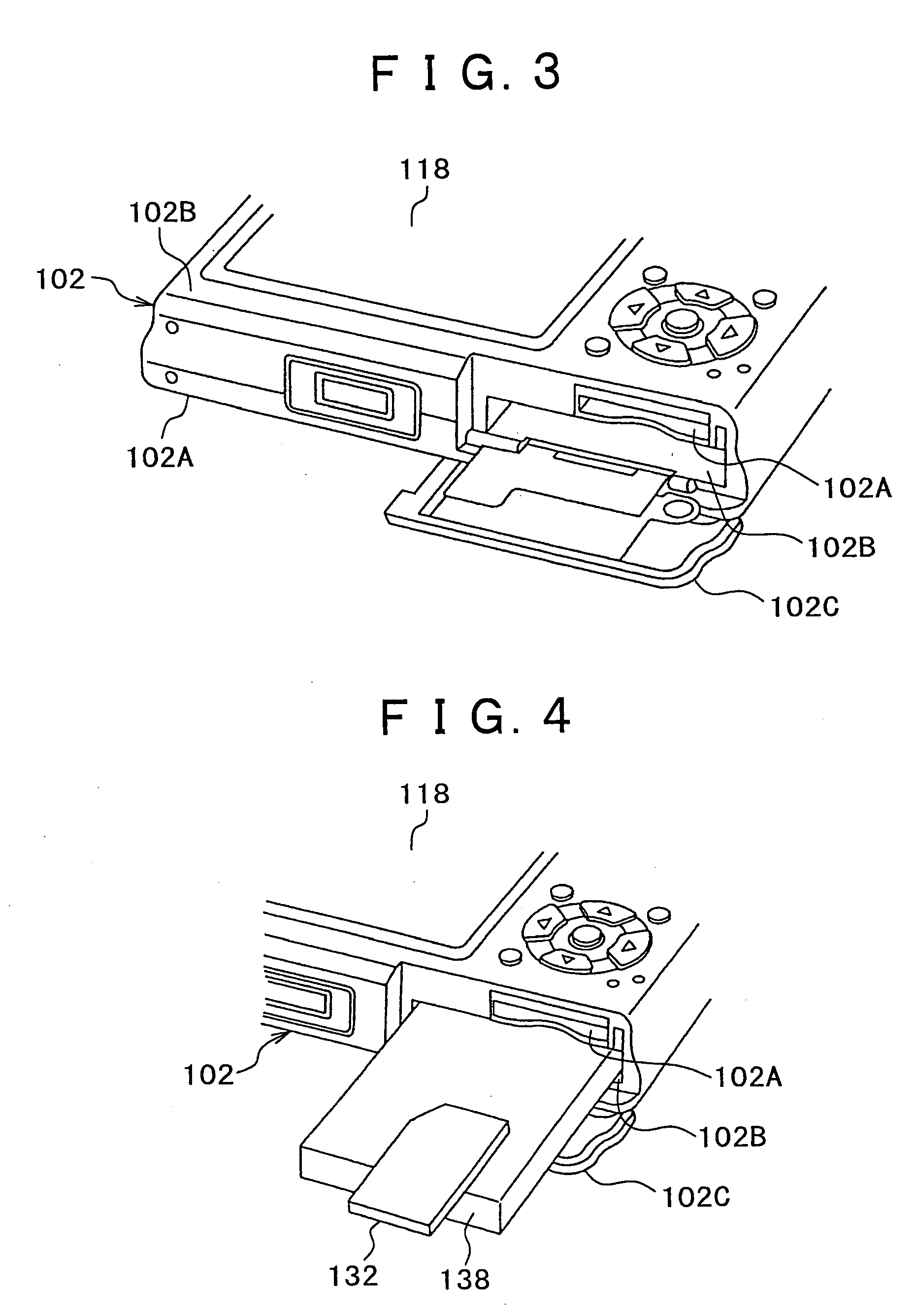
[0045]FIG. 1 is a perspective view of an imaging apparatus of the example of preferred embodiment 1 as viewed from the front side thereof, FIG. 2 is a perspective view of the imaging apparatus of the example of preferred embodiment 1 as viewed from the rear thereof, FIG. 3 is a perspective view of the imaging apparatus of the example of preferred embodiment 1 as viewed from the bottom thereof, FIG. 4 is an explanatory view aiding in explaining the state of housing of a memory card and a battery, and FIG. 5 is a block diagram showing a control system of the imaging apparatus.

[0046] As shown in FIGS. 1 and 2, an imaging apparatus 100 i...


PUM


Abstract

To provide a lens barrel and an imaging apparatus for securely connecting imaging element with imaging circuit and advantageous in terms of downsizing of devices. A plurality of first connecting terminals is provided to a bottom face of an imaging element package. A flexible circuit board is constituted by an imaging element mounting section, an extending section and a connecting section. The imaging element mounting section includes a flexible circuit board and a plurality of second connecting terminals provided on a surface of the flexible circuit board so that each of the second connecting terminals match with a corresponding first connecting terminal. A metal plate is mounted at a position where the outline of the metal plate matches the outline of the package or the outline of the package is placed in the outline of the metal plate as viewed from the thicknesswise direction of the package, on the rear face of the imaging-element mounting section.

Description

CROSS REFERENCE TO RELATED APPLICATIONS [0001] The present document claims benefit of Japanese Priority Document JP2003-359894, filed in the Japanese Patent Office on Oct. 20, 2003, the contents of which being incorporated herein by reference to the extent permitted by law. BACKGROUND OF THE INVENTION [0002] 1. Field of the Invention [0003] The present invention relates to a lens barrel and an imaging apparatus. [0004] 2. Related Art [0005] Lens barrels of the type in which imaging elements are incorporated into barrels have heretofore been provided. [0006] In this type of lens barrel and in many cases, the connecting terminals of an imaging element is connected to a hard printed circuit board by soldering, and the printed circuit board and an imaging circuit provided outside the barrel are interconnected via a flexible printed circuit board. [0007] Driving signals are supplied from the imaging circuit to the imaging element via a wiring member made of these printed circuit board an...

Claims


Application Information

Patent Timeline
Patent Type & Authority Applications(United States)
IPC IPC(8): G03B17/02H01L27/14G02B7/02H04N5/225H04N5/335H05K1/18H05K3/34
CPCH04N5/2251H04N5/2253H04N5/2254H05K1/189H05K2201/10727H05K3/3442H05K2201/056H05K2201/09181H05K2201/10121H05K3/0061H04N23/54H04N23/55H04N23/00
Inventor TANIGAWA, KOUICHIHAYASHI, TETSUO
Owner SONY CORP
Why Eureka
Try Eureka