Method for controlling laser beam power balance in laser scanning unit

Inactive Publication Date: 2005-04-21
SAMSUNG ELECTRONICS CO LTD
View PDF11 Cites 9 Cited by
  • Summary
  • Abstract
  • Description
  • Claims
  • Application Information

AI Technical Summary

Benefits of technology

[0008] The present invention solves the above drawbacks and other problems associated with the conventional arrangement. An aspect of the present invention is to provide a method for controlling laser beam power balance in a laser scanning unit wherein the optical power of the laser beam output from the laser scanni

Problems solved by technology

But it has a disadvantage of degrading the printing quality of the printer or the duplicator if the optical power between the respective laser beams scanned onto the photosensitive drum from each of the laser diodes is different.
Furthermore, time is lost because adjusting the optical power of the laser beam is a manual operation.
Therefore, there are problems in the print quality of an individual image forming apparatus having the manually operated laser scanning unit mounted due to unevenness.
Additionally, the variation in the optical power between the scanned laser beams degrades the print quality of the printer or the duplicator in the case of a multi-beam laser scanning unit wherein multiple laser beams are scanned onto the photosensitive drum from the laser scanning unit.

Method used


Image

  • Method for controlling laser beam power balance in laser scanning unit
  • Method for controlling laser beam power balance in laser scanning unit
  • Method for controlling laser beam power balance in laser scanning unit

Examples


Embodiment Construction

[0027] Certain embodiments of the present invention will now be described in greater detail with reference to the accompanying drawings.

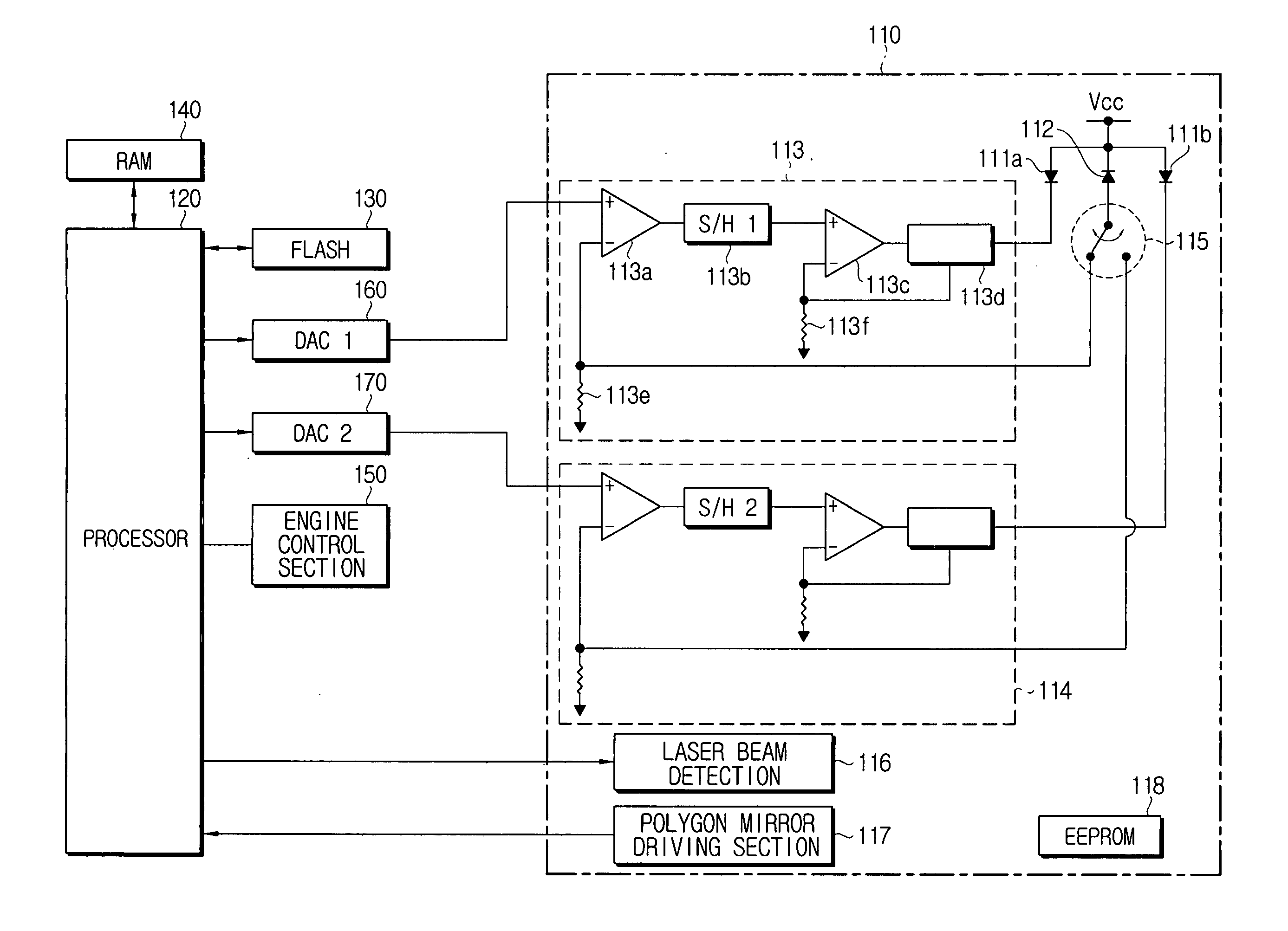
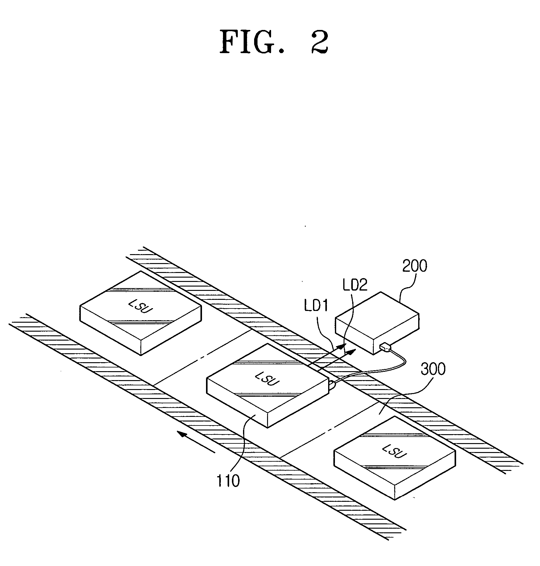
[0028] The matters defined in the description such as a detailed construction and elements are provided to assist in a comprehensive understanding of the invention. Thus, for the sake of clarity, detailed descriptions of well-known functions or constructions are omitted. As shown in FIG. 2, the method for controlling laser beam power balance in the laser scanning unit according to an embodiment of the present invention comprises the step of measuring the optical outputs of a first laser beam LD1 and a second laser beam LD2 emitted from a laser scanning unit (LSU) 110. The optical output is measured by a laser beam power meter 200 before mounting the laser scanning unit 110 on the image forming apparatus. Additionally, the step of feeding back a voltage value corresponding to the measured optical power to the laser scanning unit 110 to store the vol...


PUM


Abstract

A method for controlling a laser beam power balance in a laser scanning unit is disclosed. The method of present invention comprises the steps of obtaining a first voltage value and a second voltage value corresponding to detection time points of a first laser beam and a second laser beam, respectively, emitted from the laser scanning unit. The first voltage value and the second voltage value are recorded in the laser scanning unit. After the laser scanning unit is mounted on a image forming apparatus, a third voltage value and a fourth voltage value are obtained corresponding to the detection time points of the first laser beam and the second laser beam, respectively, emitted from the laser scanning unit by driving the laser scanning unit mounted on the image forming apparatus. The third voltage value and the fourth voltage value are compared with the first voltage value and the second voltage value, respectively, thereby correcting the control voltage controlling the laser scanning unit by that variation.

Description

CROSS-REFERENCE TO RELATED APPLICATIONS [0001] This application claims the benefit under 35 U.S.C. §119(a) of Korean Patent Application No. 2003-72270 filed Oct. 16, 2003, in the Korean Intellectual Property Office, the entire disclosure of which is incorporated herein by reference. BACKGROUND OF THE INVENTION [0002] 1. Field of the Invention [0003] The present invention relates to a method for controlling laser beam power of a laser scanning unit. More particularly, the present invention relates to a method for controlling laser beam power balance in a multi-beam laser scanning unit. [0004] 2. Description of the Related Art [0005] Generally, equipment such as a laser printer, a digital duplicator, and a multipurpose include a laser scanning unit for scanning laser beams on a photosensitive drum. The laser scanning unit comprises a laser diode for scanning a laser beam and a predetermined driving circuit for driving the laser diode. On the other hand, in order to increase the number...

Claims


Application Information

Patent Timeline
IPC IPC(8): G03G15/04B41J2/44G03G15/043H01S3/13H01S5/00H01S5/042H01S5/06H01S5/068H01S5/40H04N1/40H04N1/401
CPCH01S5/005H01S5/042H01S5/0617H04N1/4015H01S5/4031H04N1/40025H01S5/06808G03G15/04
Inventor KIM, YONG-KWON
Owner SAMSUNG ELECTRONICS CO LTD
Why Eureka
Try Eureka