Three-dimensional measurement apparatus

Inactive Publication Date: 2005-04-21
FANUC LTD
View PDF13 Cites 24 Cited by
  • Summary
  • Abstract
  • Description
  • Claims
  • Application Information

AI Technical Summary

Benefits of technology

[0009] This invention provides a three-dimensional measurement apparatus capable of ensuring the required measurement accuracy in detecting a bright portion form

Problems solved by technology

When the measurement apparatus is miniaturized by using such approach, however, the measurement accuracy (especially, the measurement accuracy in the depth direction as seen from the measurement apparatus) is liable to be worsened due to the measurement principle.
That is, in the three-dimensional measurement apparatus of the slit light projection type, there are in general conflicting requirements of miniaturizing the apparatus and improving the measurement accuracy.
According to this prior art, however, if a surface portion of a measurement object onto which slit light is irradiated is different in the degree of stain or surface roughness f

Method used


Image

  • Three-dimensional measurement apparatus
  • Three-dimensional measurement apparatus
  • Three-dimensional measurement apparatus

Examples


Example

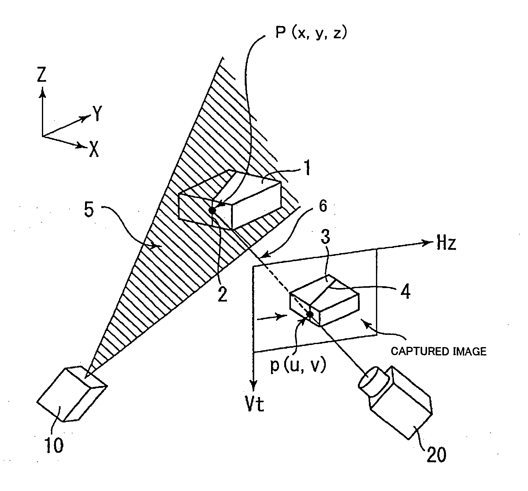
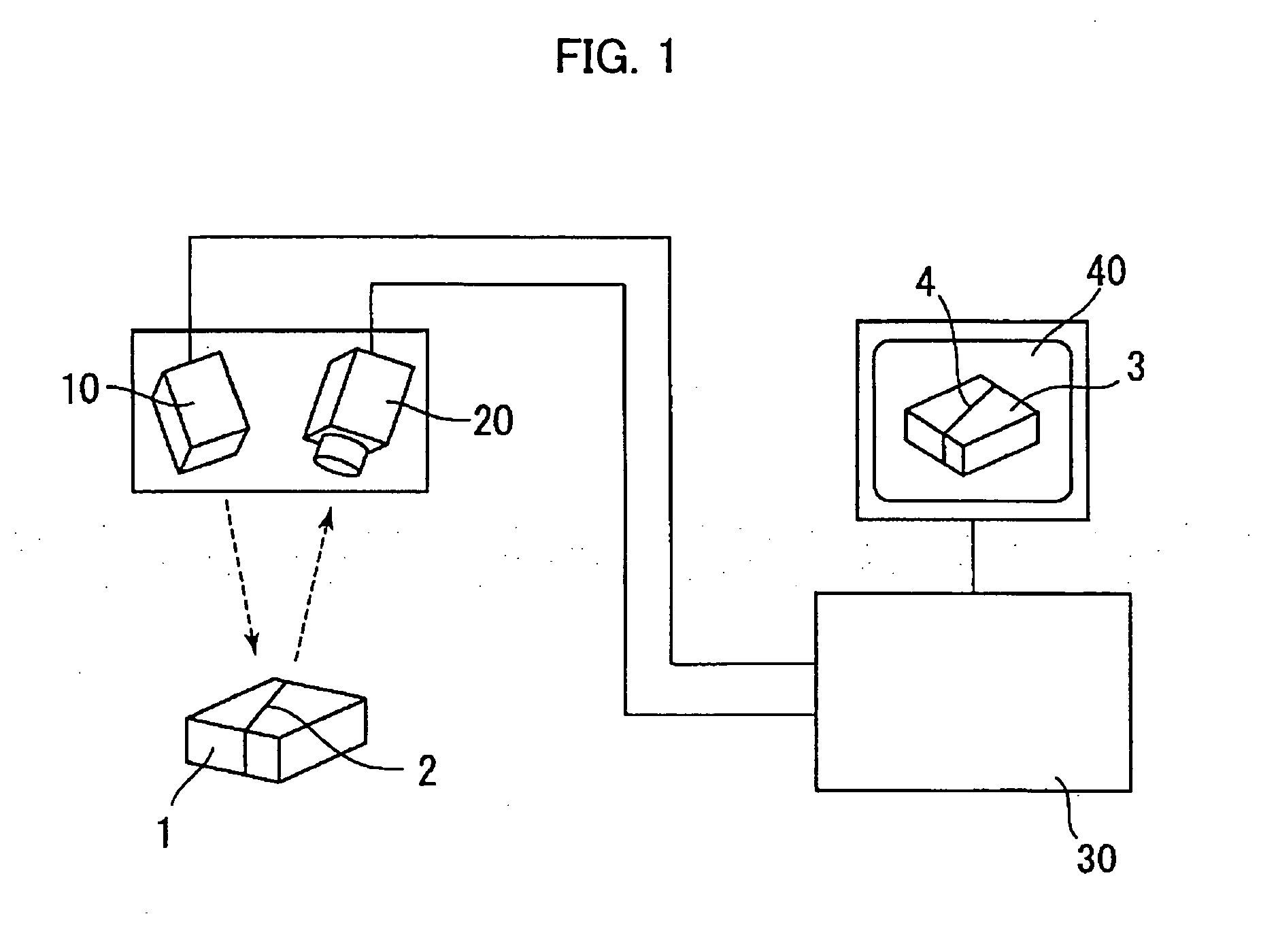
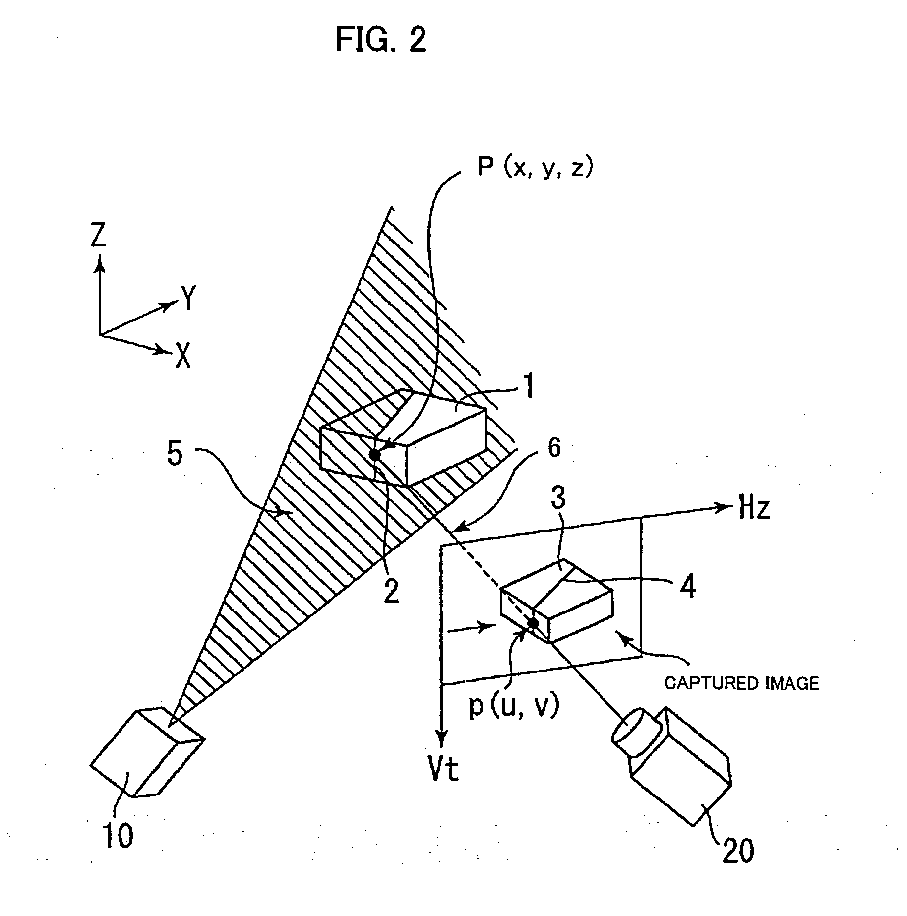
[0026] In the following, an embodiment of this invention will be explained with reference to FIGS. 1-5, in which FIG. 1 is a view showing the overall arrangement of a three-dimensional measurement apparatus according to one embodiment of this invention. In FIG. 1, a projector for projecting slit light (including pseudo slit light obtained by spot light scanning, as previously mentioned) is denoted by reference numeral 10. A photodetector 20 is disposed at a slight distance from the projector 10. The projector 10 and the photodetector 20 are united into a detection head which is used by being mounted to near an arm distal end of a robot (not shown), for instance. In a case where a robot is not used, the projector and the photodetector are disposed at appropriate places. Even in a case where a robot is used, they may be disposed at appropriate places, without being mounted to the robot.

[0027] As previously mentioned, the larger the installation distance between the projector 10 and t...


PUM


Abstract

A three-dimensional measurement apparatus of a slit light (or pseudo slit light) projection type that is adapted to prevent deterioration of measurement accuracy and to be easily miniaturized. When there is a disturbance in a region A in a distribution of pixels whose detected luminances exceed a threshold, a detected position C3 determined from a weighted average of luminances of pixels selected under a threshold condition along a scanning line traversing a bright portion image and liable to be deviated from a correct detected position line B-B is excluded from data to be used for the three-dimensional measurement, whereas detected positions C1, C2 are adopted that are determined so as to correspond to scanning lines on each of which pixels whose number falls within an allowable range are detected. The allowable range varies from Nav×αmin to Nav×αmax or from Nav−β to Nav+γ, where Nav is an average of the numbers of pixels detected on scanning lines for each of which at least one pixel is determined, and αmin, αmax, β, and γ are minimum proper ratio, maximum proper ratio, subtract number of pixels, and add number of pixels, respectively, which are set in advance as parameters.

Description

BACKGROUND OF THE INVENTION [0001] 1. Field of the Invention [0002] The present invention relates to a three-dimensional measurement apparatus in which slit light or pseudo slit light simulatedly created by scanning spot light is irradiated onto an object to form a linear bright portion, the bright portion is detected by image capturing means, and information related to three-dimensional position of the object is obtained from the position of the bright portion in the captured image. The three-dimensional measurement apparatus of the present invention is used as being mounted to a robot, for instance. [0003] 2. Description of Related Art [0004] Recently robots have been made more intelligent, whereby in many cases peripheral equipment such as a workpiece supplying and positioning apparatus is simplified. A three-dimensional measurement apparatus that recognizes the three-dimensional position, orientation, shape, size, etc. (hereinafter collectively referred to as “three-dimensional ...

Claims


Application Information

Patent Timeline
IPC IPC(8): G01B11/24G01B11/25G06T1/00
CPCG06T7/0057G01B11/25G06T7/521
Inventor AIZAWA, ATSUSHITAMURA, TOSHINARI
Owner FANUC LTD
Why Eureka
Try Eureka