Optical module, and optical transmission device

a technology of optical modules and optical transmission devices, applied in the direction of optical elements, semiconductor lasers, instruments, etc., can solve the problems of s/n ratio fall, fluctuation, etc., and achieve the effect of reducing noise and reducing light fluctuations

Active Publication Date: 2005-04-21
SEIKO EPSON CORP
View PDF10 Cites 37 Cited by
  • Summary
  • Abstract
  • Description
  • Claims
  • Application Information

AI Technical Summary

Benefits of technology

[0011] An optical module in accordance with an exemplary aspect of the present invention may include a photodetector that receives at least a part of emission light of the surface-emitting type semiconductor laser, the optical member reflecting, refracting or diffracting at least a part of emission light at the principal plane, to thereby lead reflected light, refracted light, or diffracted light, of emission light of the surface-emitting type semiconductor laser, to the photodetector. As a result, the amount of output light of the optical module and the amount of light monitored at the photodetector el

Problems solved by technology

When an optical device having polarization selectivity is present in a transmission path, fluctuations may occur in the amount of light that passes through (or

Method used


Image

  • Optical module, and optical transmission device
  • Optical module, and optical transmission device
  • Optical module, and optical transmission device

Examples


Embodiment Construction

[0024] Exemplary embodiments of the present invention will be described below with reference to the accompanying drawings.

1. First Optical Module

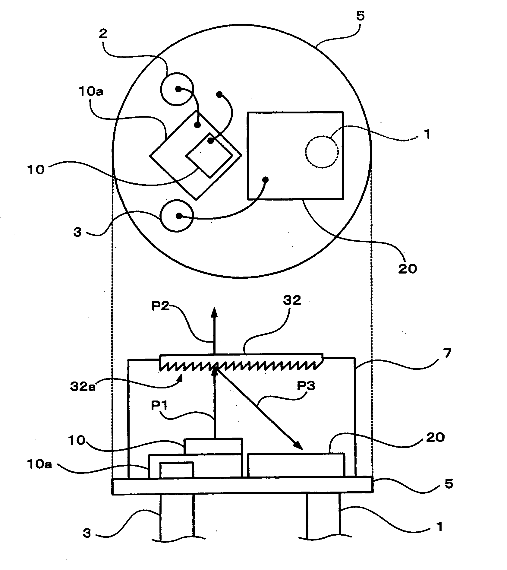
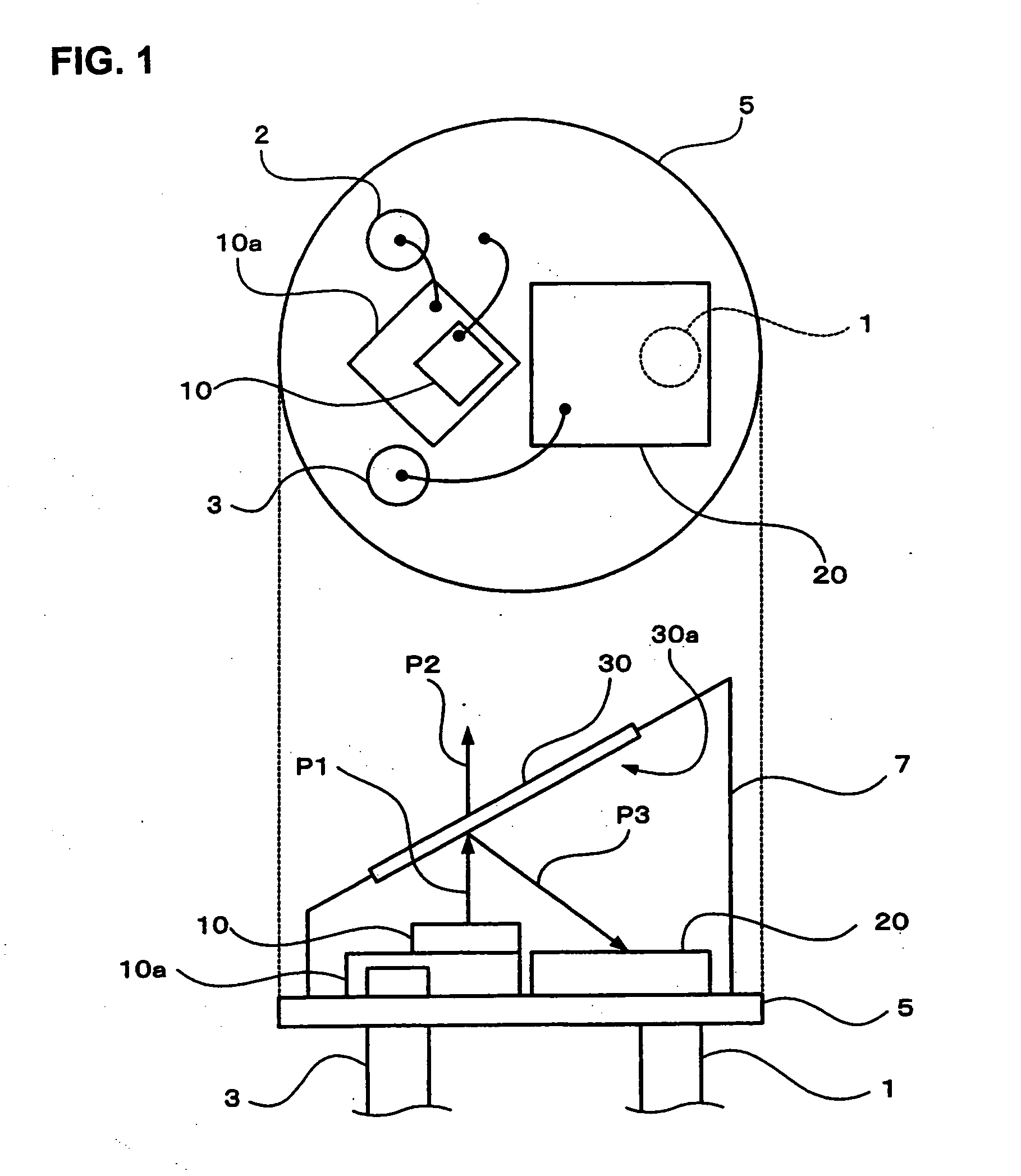
FIG. 1 schematically shows a first optical module in accordance with an exemplary embodiment of the present invention.

[0025] The optical module of the present exemplary embodiment includes a metal stem 5, and a vertical resonator type surface-emitting type semiconductor laser (a light emitting element in a broad sense: hereafter VCSEL) 10 electrically connected to the metal stem through a VCSEL submount (simply, a submount in a broad sense) 10a composed of ceramics and a metal film formed thereon (to secure insulation from the stem 5). Furthermore, a monitor PD (a photodetector in a broad sense) 20 to monitor the amount of emission light of the VCSEL 10 is disposed on the stem 5.

[0026] Also, the optical module of the present exemplary embodiment includes lead pins 1-3 for mutual transmission and reception of electrical signals with ext...


PUM


Abstract

To provide optical modules and optical transmission devices that are suitable for communication forms using multimode optical fibers, an optical module includes a surface-emitting type semiconductor laser that emits polarized light oscillating in a multimode which is preferentially oriented in two given polarization axes, and an optical member that demonstrates at least one function among a transmission function, a reflection function, a refraction function, and a diffraction function alternatively to a predetermined polarization. The optical member is disposed such that a principal plane thereof intersects with a traveling direction of emission light of the surface-emitting type semiconductor laser and a polarization axis of the polarization plane does not overlap with the polarization axes of the emission light of the surface-emitting type semiconductor laser.

Description

BACKGROUND OF THE INVENTION [0001] 1. Field of Invention [0002] Exemplary aspects of the present invention relate to optical modules and optical transmission devices having a vertical-cavity surface-emitting laser (VCSEL). [0003] 2. Description of Related Art [0004] In related art optical fiber communications systems, multimode optical fibers that have a larger core diameter than that of singlemode optical fibers and provide easy optical coupling with a light source are often used in short distance data communications up to about several hundred meters, and referred to as LAN (Local Area Network) and SAN (storage area network). [0005] When communicating with a multimode optical fiber, degradation of the S / N ratio called mode selection loss poses a problem. In order to enhance mode selection loss, in the related art, the use of a light source whose emission light has a low coherence is effective. For example, according to Laid-open Patent Application HEI 7-170231, transmission distan...

Claims


Application Information

Patent Timeline
IPC IPC(8): H01S5/068H01S5/022H01S5/183
CPCH01S5/0224H01S5/02296H01S5/0683H01S2301/02H01S5/18338H01S5/18355H01S5/18311H01L2224/16225H01L2224/48091H01S5/02257H01S5/0234H01L2924/00014
Inventor IDE, TSUGIOARITAKE, YUSUKE
Owner SEIKO EPSON CORP
Why Eureka
Try Eureka