
Variable-rate communication system with optimal filtering

Inactive Publication Date: 2005-04-21
MASSACHUSETTS INST OF TECH +1
View PDF8 Cites 17 Cited by
  • Summary
  • Abstract
  • Description
  • Claims
  • Application Information

AI Technical Summary

Benefits of technology

[0007] It is another object of this invention to provide a method of reducing a bit error rate of a digital communication system operating in a noisy channel. It is another object of this invention to provide a method of reducing intersymbol interference in a communication system.
[0010] A discovery of the present invention is that multi-rate communications can be efficiently achieved in a communication system that employs average power limited amplifiers, such as an Erbium-Doped Fiber Amplifier (EDFA), operating in saturation.
[0011] Another discovery of the present invention is that near optimum (matched) filtering can be achieved in a communication system employing an Average Power Limited (APL) amplifier operating in saturation and employing spectral or symmetric filtering. In such systems, the pulse shape of the communication signal can be adjusted prior to the APL amplifier so that the transmitted signal is matched to the receiver thereby maximizing the received energy-per-bit, without sacrificing transmitted power.
[0012] Another discovery of the present invention is that a variable rate communication system employing an average power limited amplifier operating in saturation and employing PPM signaling can provide near quantum limited performance.

Problems solved by technology

Conventional communication systems are typically peak power limited or based on peak power limited designs.
It is difficult to achieve optimum performance with peak power limited multi-rate communication systems.
Presently, optical sinc( ) filters are not commercially available.
Using different filters for each bit rate would greatly increase the cost and complexity of the multi-rate communication system.

Method used


Image

  • Variable-rate communication system with optimal filtering
  • Variable-rate communication system with optimal filtering
  • Variable-rate communication system with optimal filtering

Examples


Embodiment Construction

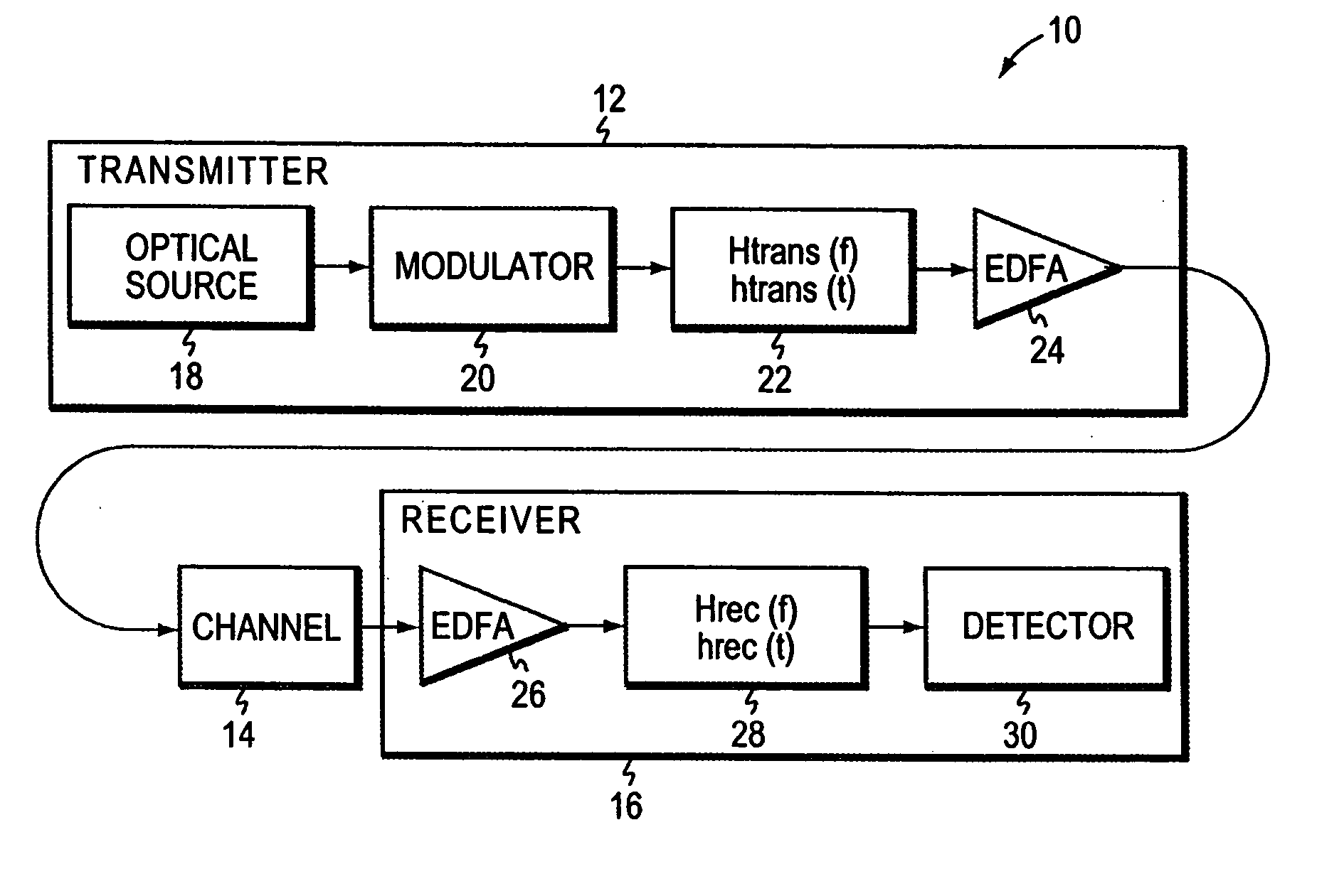
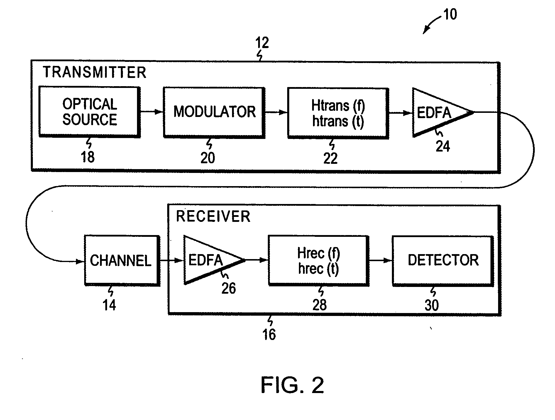
[0033]FIG. 2 illustrates a functional block diagram of one embodiment of a communication system 10 that includes spectral filtering according to the present invention. The communication system 10 includes a transmitter 12, a channel 14, and a receiver 16. The transmitter 12 includes an optical source 18, such as a CW or short pulse laser. A modulator 20 modulates the beam generated by the optical source 18.

[0034] In one embodiment, the modulator 20 is a wide-band modulator that generates a digital data signal comprising a sequence of signaling waveforms having a duty cycle and a bit rate. In another embodiment, the modulator 20 generates a digital data signal comprising a sequence of signaling waveforms having at least a first and a second duty cycle and at least a first and a second bit rate, respectively. Typically, each signaling waveform has a predetermined shape. In one embodiment, the sequence of signaling waveforms comprise m-ary pulse position modulation data.

[0035] A tran...


PUM


Abstract

A variable-bit-rate communication system is described. The communication system includes a variable-bit-rate transmitter that generates digital data at a first or a second bit rate and a variable-bit-rate receiver that receives the digital data. The digital data comprises a sequence of signaling waveforms having a first or a second duty cycle, respectively, wherein each signaling waveform has the same shape.

Description

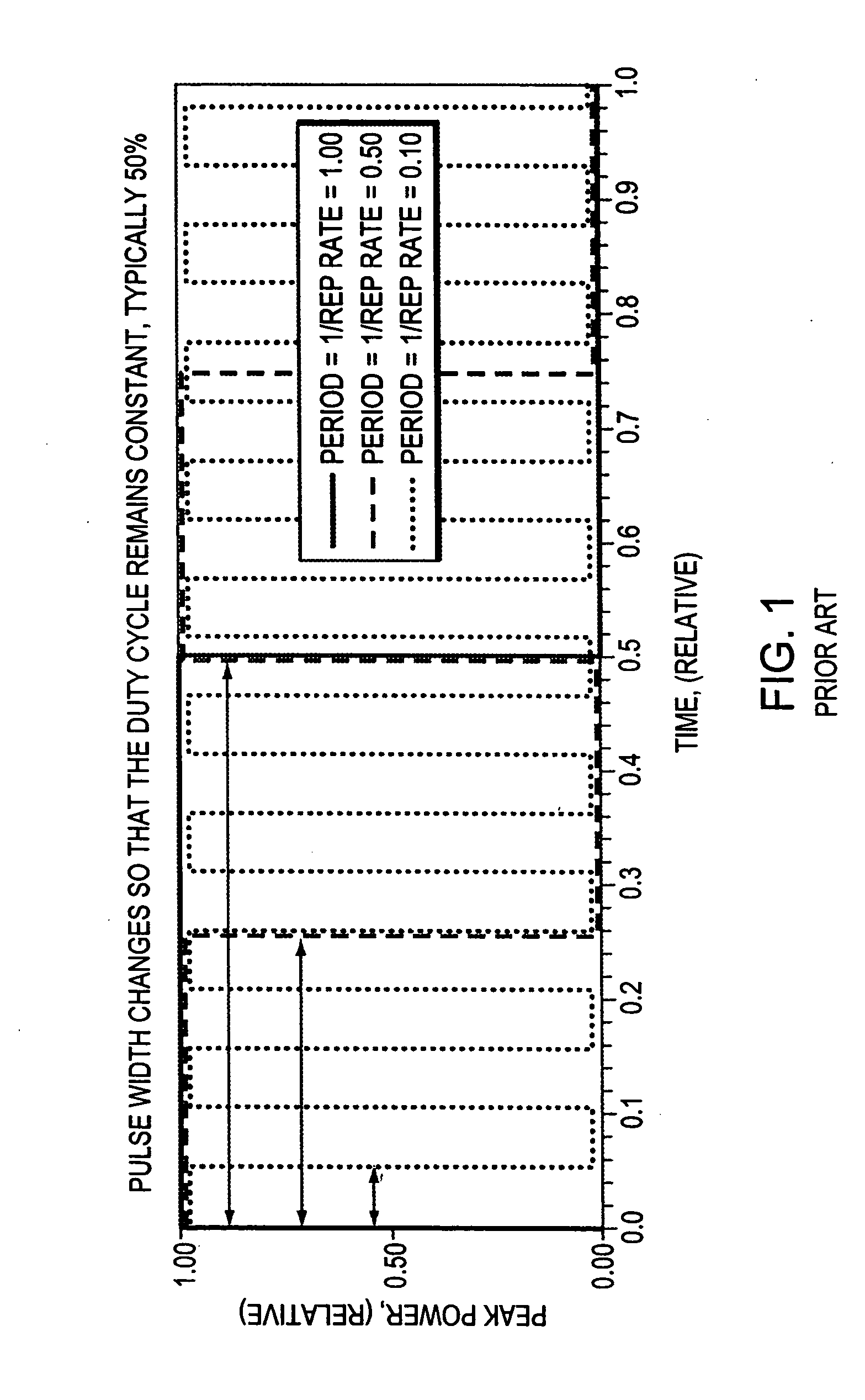
GOVERNMENT SUPPORT [0001] This invention was made with government support under Contract Number F19628-95-C-0005 awarded by the U.S. Air Force. The government has certain rights in the invention.FIELD OF THE INVENTION [0002] The invention relates generally to the field of optical communications. In particular, the invention relates to a variable-bit-rate optical communication system and to methods of operating a variable-bit rate optical communication system with nearly optimum filtering. BACKGROUND OF THE INVENTION [0003] Conventional communication systems are typically peak power limited or based on peak power limited designs. In operation, these systems maximize transmitted power by modifying the pulse width for each particular bit rate while maintaining a constant duty cycle. [0004]FIG. 1 illustrates a prior art method of increasing the energy-per-bit in a peak power limited multi-rate communication system. In this prior art method, the pulse width changes in proportion to the r...

Claims


Application Information

Patent Timeline
IPC IPC(8): H04B10/155H04L1/00
CPCH04L1/0002H04B10/505
Inventor CAPLAN, DAVID O.STEVENS, MARK L.BOROSON, DON M.
Owner MASSACHUSETTS INST OF TECH
Learn More