
Refrigerant compressor and friction control process therefor

a compressor and friction control technology, applied in the direction of machines/engines, liquid fuel engines, positive displacement liquid engines, etc., can solve the problem of not reducing the sliding friction between the compressor parts to a sufficient degree, and achieve the effect of reducing engine load, reducing sliding friction, and improving fuel efficiency

Active Publication Date: 2005-04-21
NISSAN MOTOR CO LTD
View PDF23 Cites 32 Cited by
  • Summary
  • Abstract
  • Description
  • Claims
  • Application Information

AI Technical Summary

Benefits of technology

[0005] It is therefore an object of the present invention to provide a refrigerant compressor having compressor parts slidably opposed to each other so as to attain a lower friction coefficient and higher seizure / wear resistance between the compressor parts and, e.g. when used in an automotive air conditioner, obtain improvements in engine fuel efficiency upon reduction of engine load. It is also an object of the present invention to provide a process for controlling sliding friction between the compressor parts of the refrigerant compressor.
[0006] As a result of extensive research, it has been found by the present inventors that an opposed pair of compressor parts shows excellent low-friction characteristics and durability in the presence of a specific lubricant when either or both of the opposed sliding parts are covered with thin coatings of hard carbon low in hydrogen content. The present invention is based on the above finding.

Problems solved by technology

Under such lubrication conditions, however, the sliding friction between the compressor parts is not reduced to a sufficient degree.

Method used


Image

  • Refrigerant compressor and friction control process therefor
  • Refrigerant compressor and friction control process therefor
  • Refrigerant compressor and friction control process therefor

Examples


first embodiment

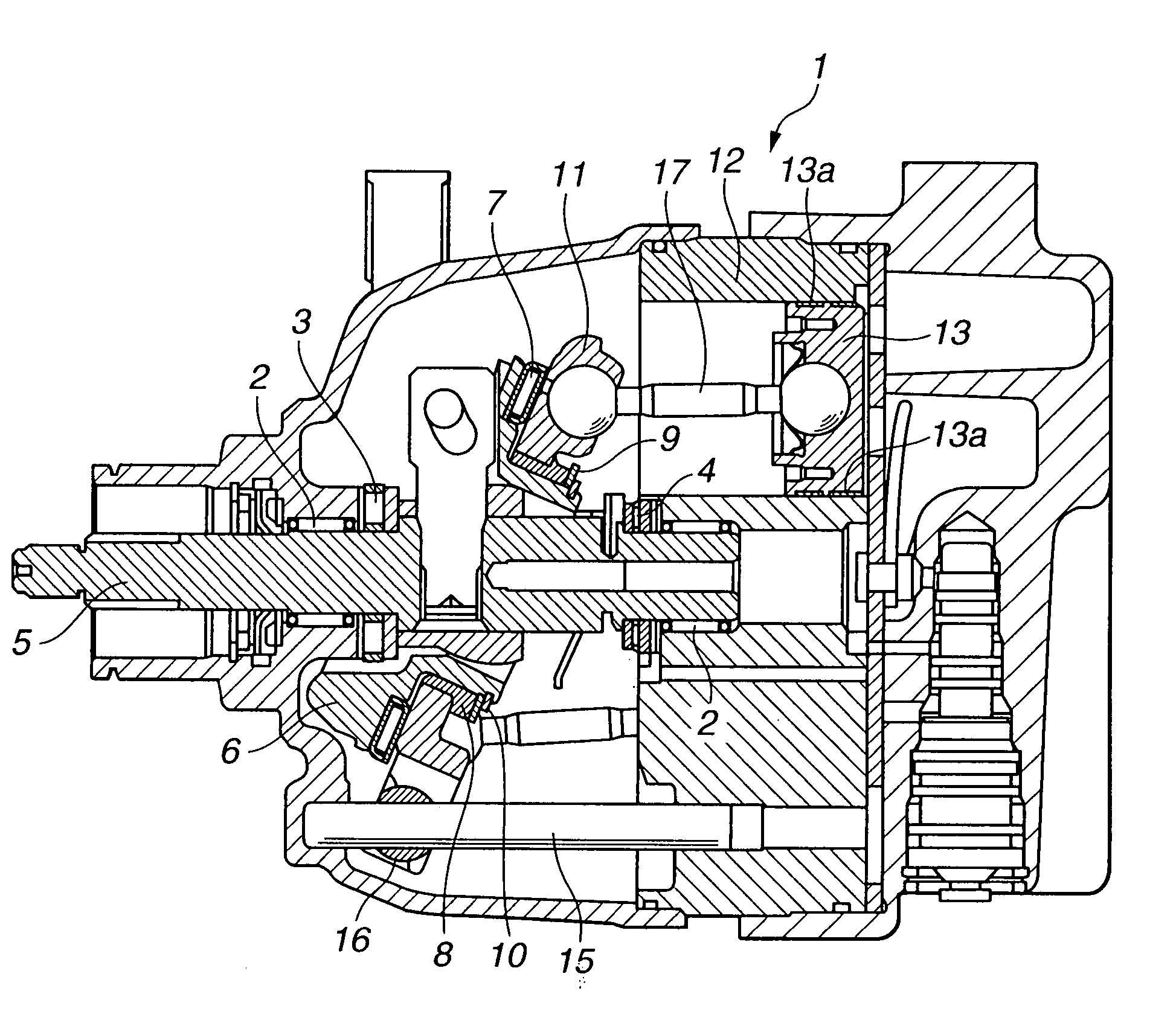
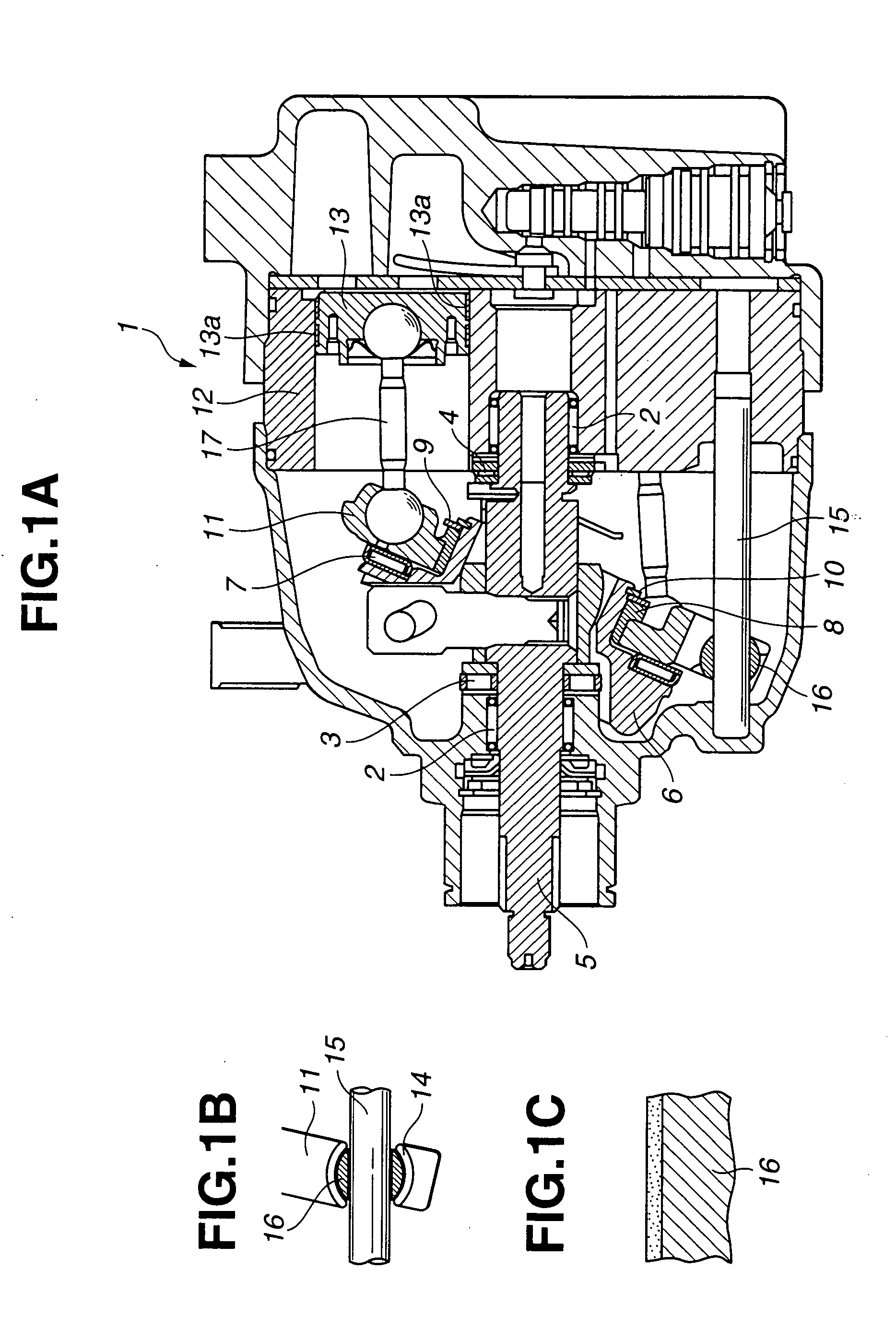
[0019] There is provided in the present invention wobble-plate type (variable displacement type) refrigerant compressor 1 as shown in FIGS. 1A and 1B. Refrigerant compressor 1 includes front and rear main bearings 2, front thrust bearing 3, rear thrust bearing 4, drive shaft 5, journal 6, journal thrust bearing 7, sleeve bearing 8, journal thrust spacer 9, C-ring10, socket plate (wobble plate) 11, cylinder 12, piston 13, shoe 14, guide pin 15, guide ball 16 and piston rod 17. Drive shaft 5 is supported by main bearings 2 and thrust bearings 3 and 4 so as to rotate together with journal 6. Socket plate 11 is supported by journal thrust bearing 7 and sleeve bearing 8 so as to rotate relative to journal 6, and is held with journal thrust spacer 9 and C-ring 10 so as not to fall off its position. Further, socket plate 11 is connected to piston 13 by piston rod 17. Piston 13 has piston ring 13a formed at an outer cylindrical face thereof, and reciprocates within cylinder 12 for intake, c...

second embodiment

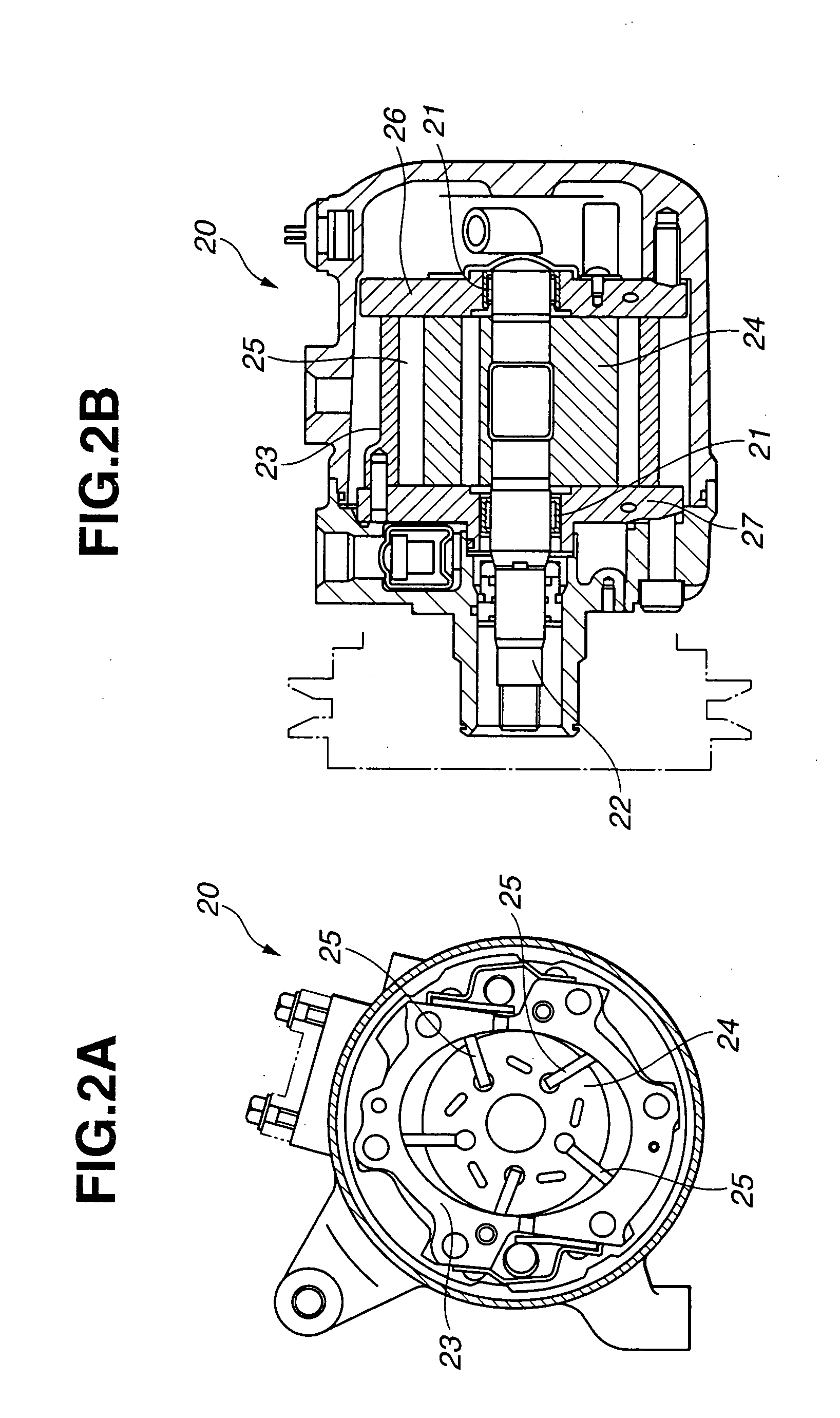
[0021] There is provided in the present invention rotary-vane type refrigerant compressor 20 as shown in FIGS. 2A and 2B. Refrigerant compressor 20 includes two bearings 21, rotor shaft 22, elliptic ring 23, rotor 24, a plurality of vanes 25 and side plates 26 and 27. Rotor shaft 22 is rotatably supported by bearings 21. Rotor 24 is fixed to rotor shaft 22 such that rotor 24 rotates within ring 23. Vanes 25 are retractably attached to rotor 24 so as to have outer edges held in sliding contact with the inner cylindrical face of ring 23. Side plates 26 and 27 are disposed to close both open ends of ring 23, respectively. For lubrication, a specific lubricant is supplied to the sliding interface between bearing 21 and rotor shaft 22, the sliding interface among the outer cylindrical face of rotor 24, the outer edges of vanes 25 and the inner cylindrical face of ring 23, the sliding interface between rotor 24, both ends of vanes 25 and side plates 26 and 27 and the sliding interface bet...


PUM

PropertyMeasurementUnit
Percent by atomaaaaaaaaaa

Abstract

There is provided a refrigerant compressor including compressor parts having sliding portions slidable relative to each other and a refrigeration oil applied to the sliding portions of the compressor parts. At least one of the sliding portions of the compressor parts has a hard carbon coating formed thereon with a hydrogen content of 20 atomic % or less.

Description

CROSS-REFERENCE TO RELATED APPLICATIONS [0001] The present application is related to the following applications: U.S. patent application Ser. No. 09 / 545,181 (based on Japanese Patent Application No. 11-102205 filed on Apr. 9, 1999); U.S. patent application Ser. No. 10 / 468,713, which is the national phase of PCT Application No. JP02 / 10057 (based on Japanese Patent Application No. 2001-117680 filed on Apr. 17, 2001); U.S. patent application Ser. No. 10 / 355,099 (based on Japanese Patent Application 2002-45576 filed on Feb. 22, 2002); U.S. patent application Ser. No. 10 / 682,559 (based on Japanese Patent Application No. 2002-302205 filed on Oct. 16, 2002); and U.S. patent application Ser. No. 10 / 692,853 (based on Japanese Patent Application No. 2002-322322 filed on Oct. 16, 2002).BACKGROUND OF THE INVENTION [0002] The invention relates to a refrigerant compressor having compressor parts slidable relative to each other with a lower friction coefficient in the presence of a specific lubric...

Claims


Application Information

Patent Timeline
IPC IPC(8): F04B39/00C10M101/02C10M129/06C10M129/08C10M129/16C10M129/28C10M129/68C10M169/04C10M171/00C10N40/30F04B27/08F04B27/10F04B39/02F04C18/344F16C29/02F16C33/10F16C33/24F16C33/34F16C33/62F16C33/66
CPCC10M171/008F05C2253/12C10M2207/022C10M2207/0225C10M2207/289C10M2209/1033C10M2209/1045C10N2230/06C10N2240/30C10N2280/00F04B27/1036F04B39/0215F04C18/3446F04C2230/91F05C2203/0808F05C2203/0882C10M2203/1006C10N2030/06C10N2040/30C10N2080/00
Inventor UENO, TAKAFUMIKANO, MAKOTOHAMADA, TAKAHIRO
Owner NISSAN MOTOR CO LTD
Features
  • Generate Ideas
  • Intellectual Property
  • Life Sciences
  • Materials
  • Tech Scout
  • Unparalleled Data Quality
  • Higher Quality Content
  • 60% Fewer Hallucinations
Learn More