Organic electroluminescent device and production process thereof

a technology of electroluminescent devices and electroluminescent devices, which is applied in the direction of luminescnet screens, discharge tubes, instruments, etc., can solve the problems of inability to select the electrode material for the alloy-based electrode, inability to oxidize and stabilize magnesium, and inability to meet the requirements of the application of the electrode, etc., to achieve the effect of stable device properties, reducing the driving stability of the el device, and increasing the driving voltag

Active Publication Date: 2005-04-21
ROHM CO LTD +1
View PDF21 Cites 153 Cited by
  • Summary
  • Abstract
  • Description
  • Claims
  • Application Information

AI Technical Summary

Benefits of technology

The present invention provides an organic EL device with improved stability and driving performance compared to prior art devices. This is achieved by excluding reactive metals from the layer adjacent to the cathode and making them stable and oxidized state in the vicinity of the cathode. Additionally, a thermal reducing reaction generating layer is inserted between the cathode and metal-doping layer to prevent the problem of thermal reduction reaction. The metal-doping layer acts as a low resistance electron-transporting layer and can prevent short circuiting between the electrodes and control the profile of the spectrum.

Problems solved by technology

The patent text discusses the use of a two-layered cathode in the electron injection of organic light-emitting diodes (EL devices) and the limitations of conventional methods in selecting the electrode materials. The technical problem addressed in the patent is the deterioration of the EL device caused by the use of reactive metals in vacuum and the inability to regulate the layer thickness. The patent proposes a method for improving the electron injection and stability of the cathode by forming an organometallic complex compound containing a metal ion and an electron-transporting organic compound in the organ layer. The patent text also discusses the reaction between the resulting metal and the organic layer in the C-T complex and the effect on the stability of the resulting EL device.

Method used


Image

  • Organic electroluminescent device and production process thereof
  • Organic electroluminescent device and production process thereof
  • Organic electroluminescent device and production process thereof

Examples


reference example 1

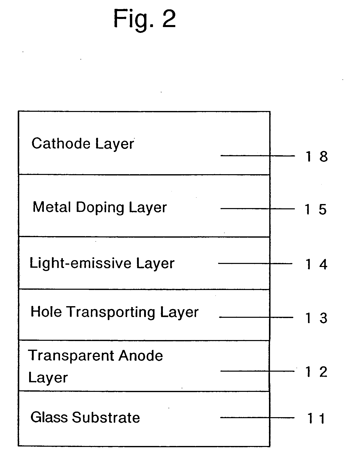
[0079] Reference Example 1 is intended to explain the production of the prior art organic EL device, described in Japanese Unexamined Patent Publication (Kokai) No. 10-270171, in which the low resistance electron-transporting layer (metal doping layer) is in contact with the cathode layer and can also act as an electron injection layer. The EL device produced in this reference example is the organic EL device having the lamination structure of FIG. 2, and it includes a glass substrate 11 having coated thereon an ITO (indium-tin oxide, product on Nippon Sheet Glass Co., Ltd.) having a sheet resistance of about 10 Ω / □ as a transparent anode electrode 12. Alpha(α)-NPD having a hole transporting property, represented by the following formula:

is deposited onto the ITO-coated glass substrate 11 under vacuum of about 10−6 Torr (1 Torr≈133.32 Pa) and at the deposition rate of about 2 Å / sec to form a hole transporting layer 13 having a thickness of about 500 Å. Next, an aluminum complex o...

reference example 2

[0082] Reference Example 2 is intended to explain the production of the prior art organic EL device, described in Japanese Unexamined Patent Publication (Kokai) No. 11-233262, in which the low resistance electron-transporting layer (metal doping layer) is omitted from the device and the reducing reaction generating layer (e) can act as an electron injection layer.

[0083] The EL device produced in this reference example is a organic EL device having the lamination structure of FIG. 7, in which a transparent anode electrode 22 and a hole transporting layer 23 are deposited on a glass substrate 21 under the same conditions as those applied in Reference Example 1. Subsequently, the above-described Alq is deposited to form a light- emissive layer 24 having a thickness of about 700 Å.

[0084] An organometallic complex compound containing lithium (alkaline metal) ions, i.e., mono(8-quinolinato) lithium complex (hereinafter, briefly referred to as “Liq”) represented by the following formula:...

example 1

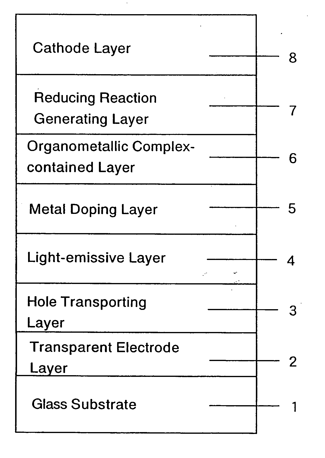
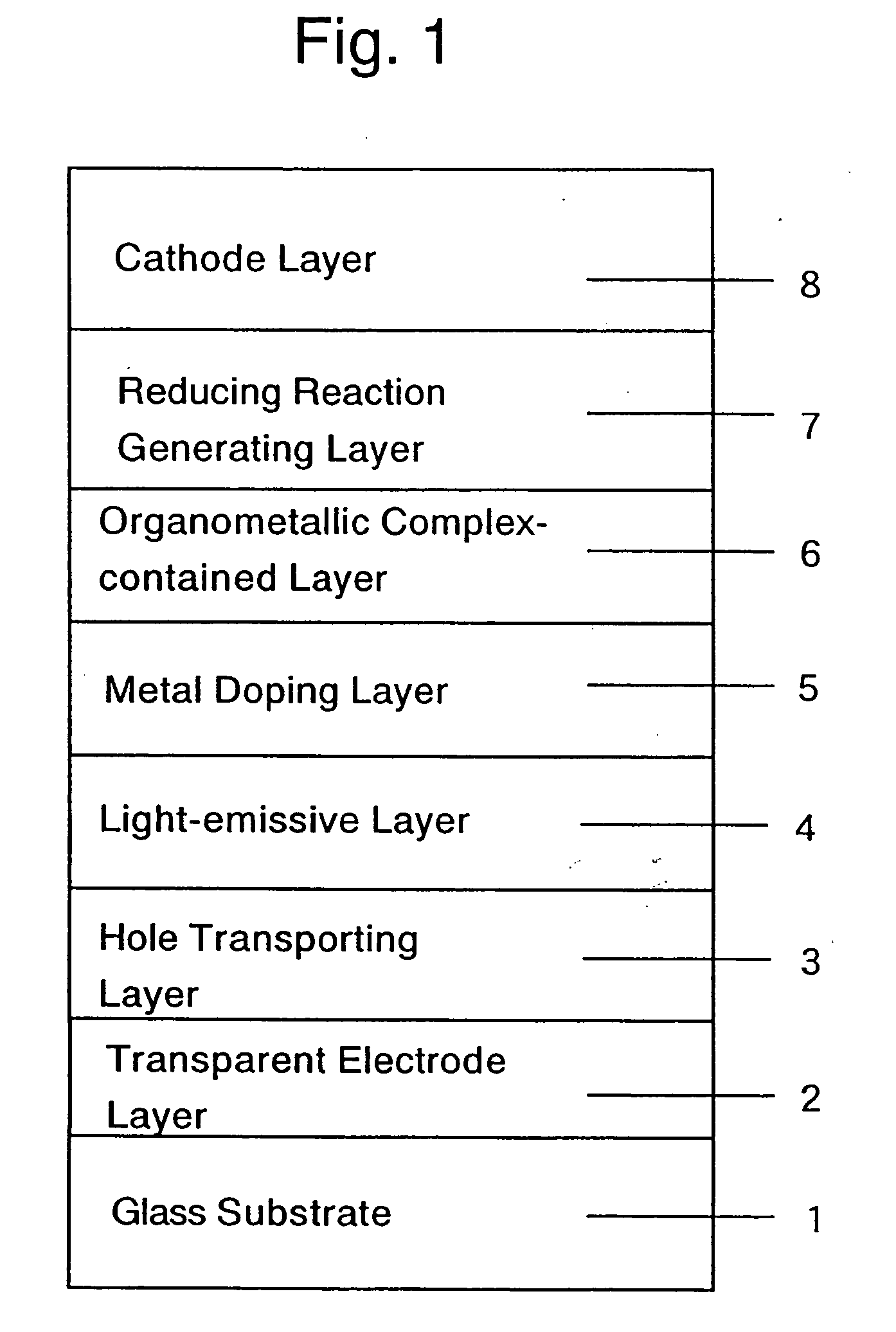
[0086] Example 1 illustrates the production of the organic EL device, according to the present invention, in which the organometallic complex-contained layer is formed only from an organometallic complex. The organic EL device having the lamination structure of FIG. 8 is produced as follows. On a glass substrate 31, a transparent anode electrode 32, a hole transporting layer 33, a light- emissive layer 34 and a metal doping layer (low resistance electron-transporting layer, i.e., co-deposition layer of BCP and Cs) 35 are deposited in sequence under the deposition conditions similar to those applied in Reference Example 1. Thereafter, as in Reference Example 2, Liq is deposited to form an organometallic complex-contained layer 36 having a thickness of about 25 Å. Finally, an aluminum (Al; work function of 4.2 eV) which is a thermally reducible metal capable of reducing a metal ion (Li+) in the Liq in a vacuum to the corresponding metal (Li) is deposited at a deposition rate of about ...


PUM

PropertyMeasurementUnit
Thicknessaaaaaaaaaa
Energyaaaaaaaaaa
Electrical resistivityaaaaaaaaaa

Abstract

An organic electroluminescent device including a substrate, the substrate includes, laminated thereon, an anode layer; an organic structure including at least one light- emissive layer or at least one light-emissive unit having at least one light-emissive layer; a low resistance electron-transporting layer including a mixed layer of an electron-donating metal dopant and an organic compound; an organometallic complex-contained layer including an organometallic complex compound containing at least one metal ion selected from the group having an alkaline metal ion, an alkaline earth metal ion and a rare earth metal ion; a reducing reaction generating layer; and a cathode layer, in that order. At least one of the anode layer and the cathode layer is transparent. The reducing reaction generating layer is a layer produced by depositing on the organometallic complex- contained layer a thermally reducible metal capable of reducing a metal ion in the organometallic complex compound in a vacuum to the corresponding metal, followed by causing an oxidation-reduction reaction therebetween.

Description


Claims


Application Information

Patent Timeline
Owner ROHM CO LTD
Why Eureka
Try Eureka