Wireless antenna traffic matrix

Inactive Publication Date: 2005-04-21
CSS ANTENNA
View PDF13 Cites 18 Cited by
  • Summary
  • Abstract
  • Description
  • Claims
  • Application Information

AI Technical Summary

Benefits of technology

[0013] These and other objects are herein accomplished by a beam shaping antenna matrix for use in wireless cell towers that facilitates a simple manual configuration procedure by a wireless operator based on selection of a desired beam size and point of directio

Problems solved by technology

However, creation of new cells involves increased equipment and real estate procurement costs for more sites.
This can be an unduly expensive proposition.
User demographics may change to the point where the base transceiver stations have insufficient capacity to deal with demand from a localized area.
Prior art beam shaping solutions utilize complex beam-forming devices (LPAs, controllable phase shifters, etc.), many of wh

Method used


Image

  • Wireless antenna traffic matrix
  • Wireless antenna traffic matrix
  • Wireless antenna traffic matrix

Examples


Example

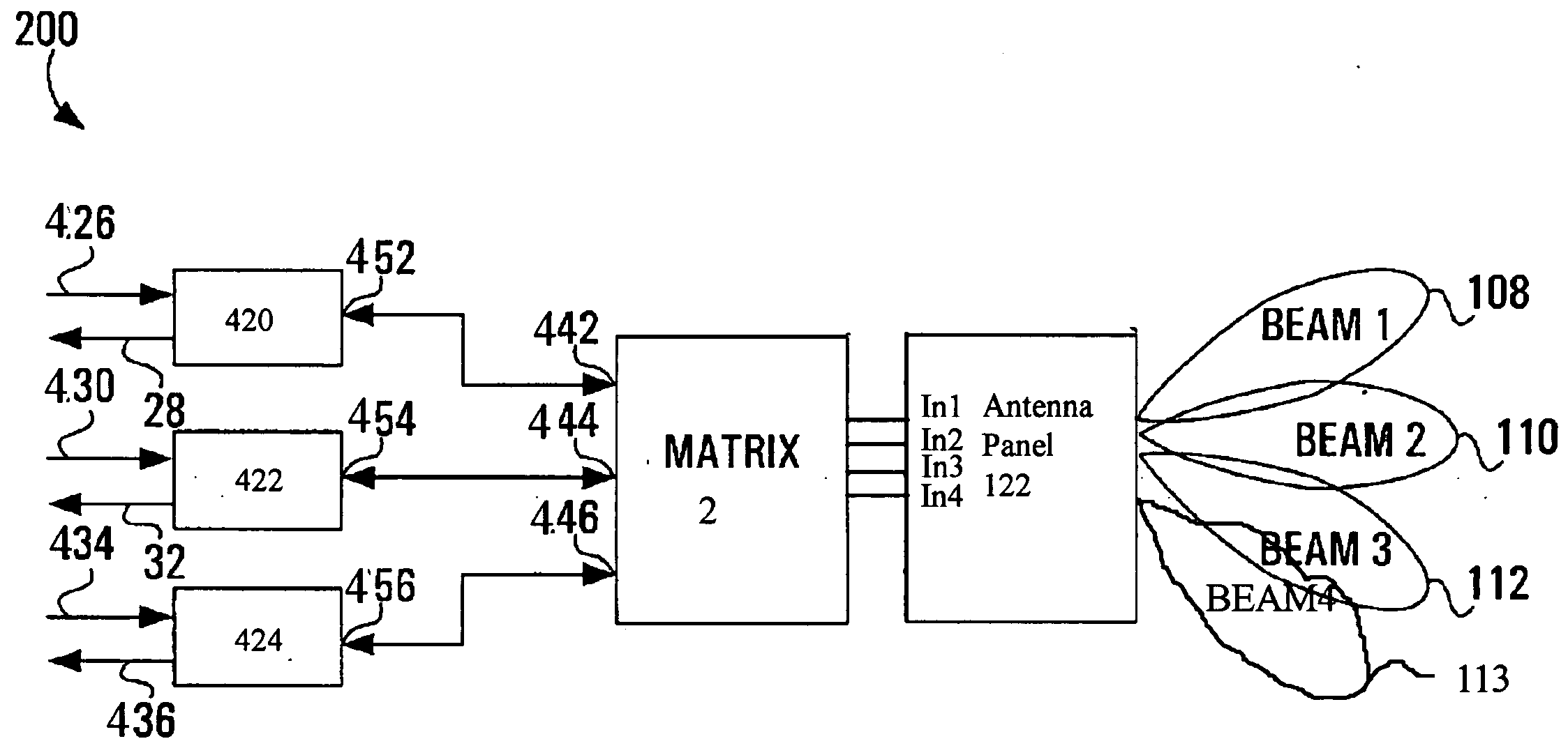
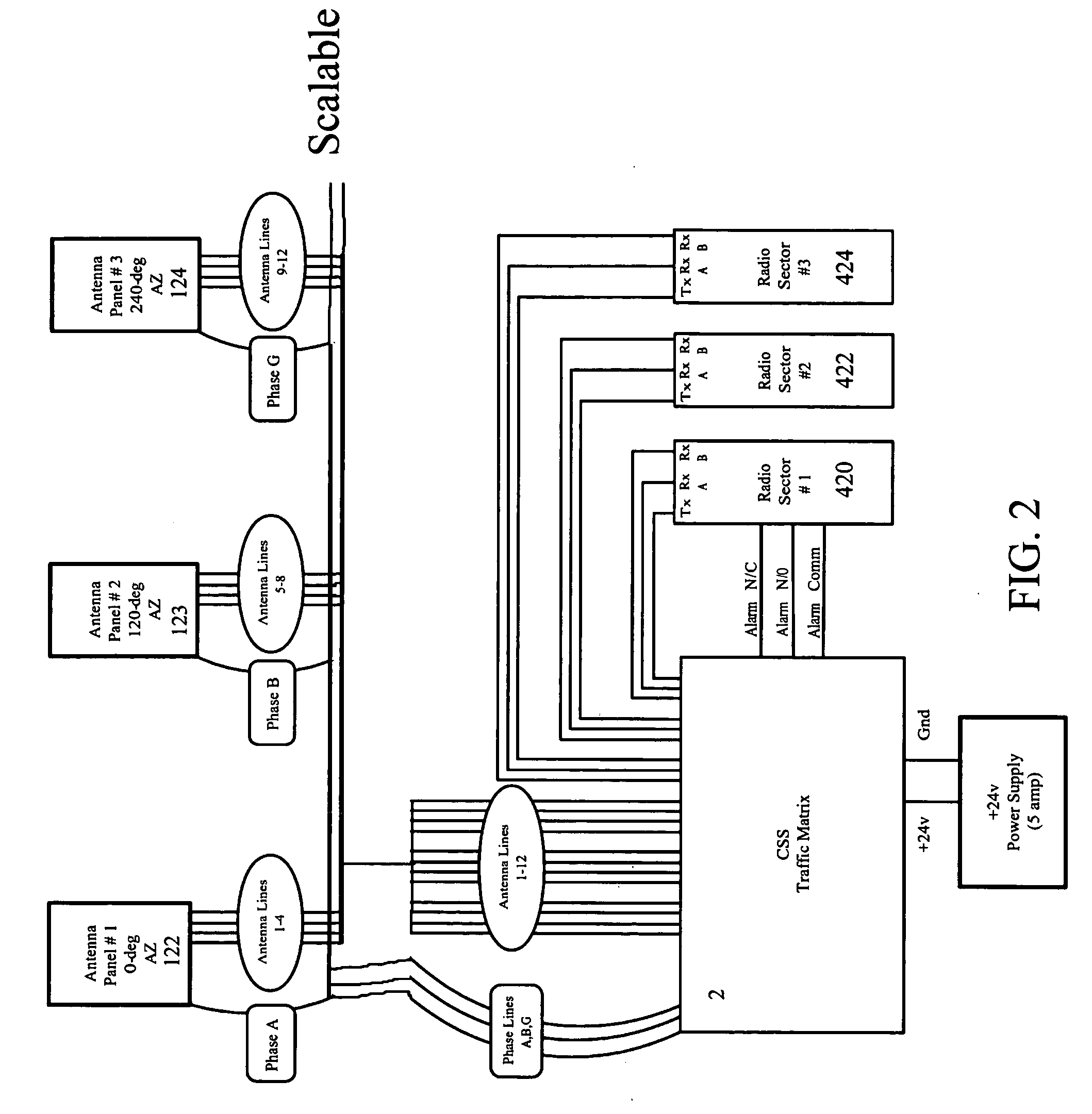
[0023] The present invention is a wireless traffic matrix 2 incorporating a beam switching architecture suitable for use with a conventional wireless antenna system. The present beam switching architecture operates to accept signals from an antenna array and adaptively form antenna beams having desired (reconfigurable) attributes. The switching architecture allows a tower operator to easily reconfigure diversity coverage at a patch panel located in the tower base. The antenna matrix 2 is simple, easy to reconfigure, and relatively fault-free (in comparison to auto-switching diversity arrays.

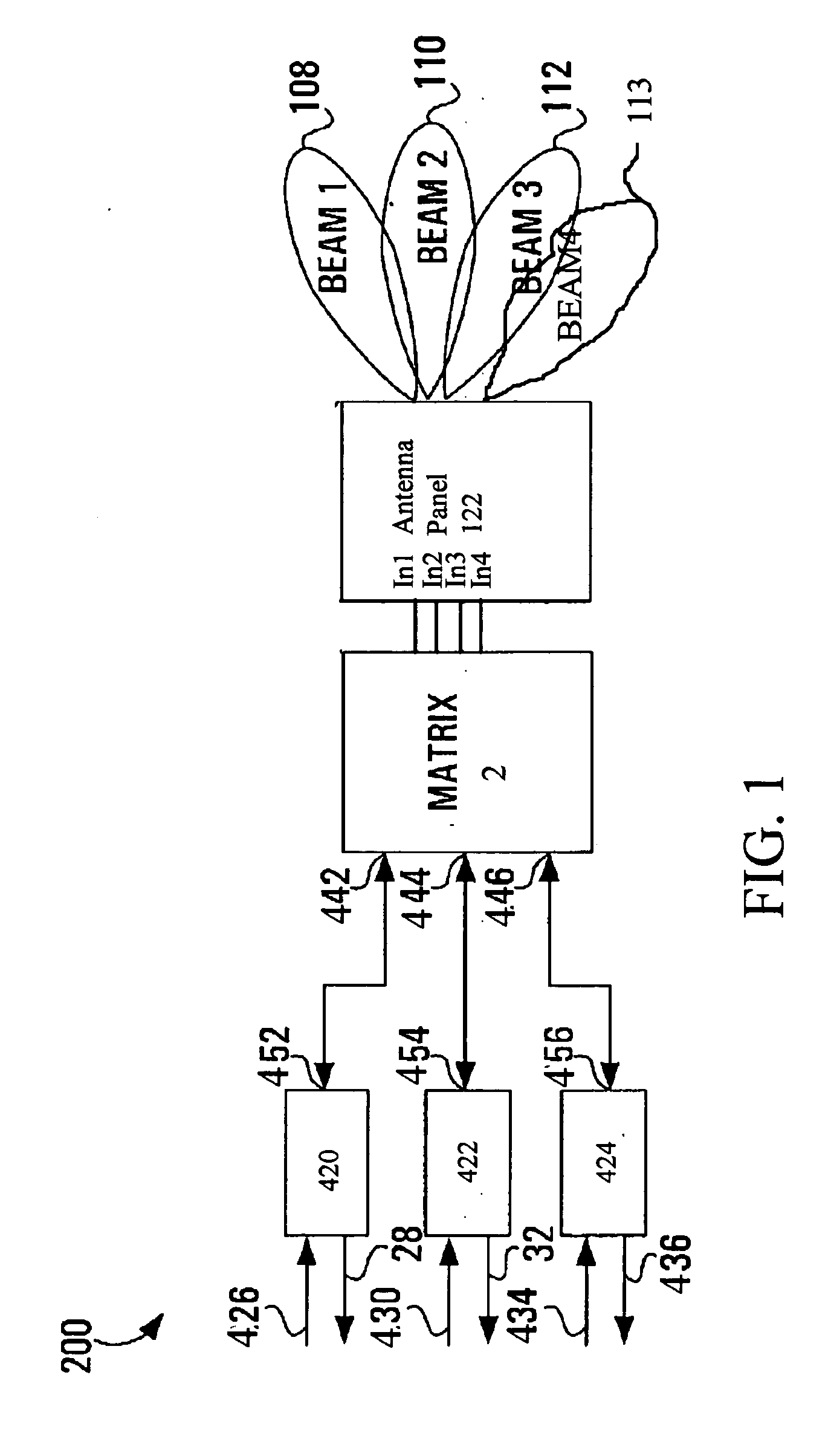
[0024] To this end, FIG. 1 shows an otherwise conventional four-port antenna system 200 comprised of a single antenna panel 122 to cover an area with four beams inclusive of a first beam 108, second beam 110, third beam 112, and fourth beam 113 (there may be more or less beams as desired). Conventional wireless systems will employ any number of antenna panels each having any number of antenna el...


PUM


Abstract

A beam shaping antenna matrix for use in wireless cell towers that is manually-configured at a patch panel by a wireless operator based on selection of a desired beam size and point of direction. The traffic matrix allows a wireless operator to sculpt and resculpt the beams to accommodate demographic or other changes preferably without a large amount of hardware or intensive processing capability.

Description

CROSS-REFERENCE TO RELATED APPLICATIONS [0001] The present application derives priority from U.S. Provisional Application Ser. No. 60 / 512,390 filed: Oct. 17, 2003.BACKGROUND OF THE INVENTION [0002] 1. Field of the Invention [0003] The present invention relates to antennas for use in a wireless communications systems and, more particularly, to a simplified traffic matrix for balancing wireless traffic at an antenna station. [0004] 2. Description of the Background [0005] Typical wireless systems divide geographical areas into a plurality of adjoining cells, and each cell is provided with a wireless cell tower. The frequency band within which wireless radio systems operate is limited in band width, and so available carrier frequencies must be used efficiently in order to provide sufficient user capacity in the system. [0006] One solution to increase call carrying capacity is to create more cells of smaller area, and / or add more carriers to existing cells. However, creation of new cells...

Claims


Application Information

Patent Timeline
IPC IPC(8): H01Q1/24H01Q3/40H01Q25/00H04M1/00
CPCH01Q1/246H01Q25/00H01Q3/40
Inventor SOBCZAK, DAVID M.BENALLA, ABDELAZIZCASE, GREGORY
Owner CSS ANTENNA
Why Eureka
Try Eureka