Adjustable surgical cutting instrument and cam system for use in same

a surgical cutting and cam system technology, applied in the field of surgical cutting instruments, can solve the problems of affecting the surgeon's visual access to the surgical site, the angle of the surgical cutting member cannot be adjusted relative to the handpiece, and the limitations of the cam system in the conventional surgical cutting instrument, so as to improve the ergonomics, reduce hand fatigue, and improve control

Inactive Publication Date: 2005-04-21
SUROS SURGICAL SYST
View PDF27 Cites 36 Cited by
  • Summary
  • Abstract
  • Description
  • Claims
  • Application Information

AI Technical Summary

Benefits of technology

[0008] An adjustable cam and follower system for a surgical device is provided that includes a tri-dimensional rotatable cam member having a rotational input and a cam surface, the contour of which is defined by at least one radius of varying length. The system further includes a follower selectively moveable linearly, the follower configurable to ride substantially upon the cam surface as the cam rotates. Accordingly, the cam and follower system produces smooth reciprocating movement in the follower. In an embodiment, the cam and follower system is contained within a handpiece having an ergonomic member attachable thereto. The cam and follower system improves ergonomics for a surgeon by enabling the surgeon to adjust the angle of the surgical device thereby modifying the cutting angle of the surgical device. Furthermore, the ergonomic member enables a reduction in hand fatigue by enabling better control when manipulating the surgical device during surgical procedures.

Problems solved by technology

Unfortunately, the cam systems in conventional surgical cutting instruments are limited in that the operating plane of the surgical cutting member is fixed in relation to the rotational axis of the cam.
In other words, the angle of the surgical cutting member cannot be adjusted relative to the handpiece.
Among other limitations, the inability to adjust the angle between the surgical cutting member and the handpiece may impair a surgeon's visual access to the surgical site.
Furthermore, the inability to modify the cutting member angle relative to the handpiece precludes a surgeon from adjusting the surgical instrument to ergonomically fit his / her hand.
Moreover, although the method of holding the handpiece in the same manner as a pencil is intuitive, it does not provide the best control when manipulating the handpiece during long and / or awkward surgical procedures.
While these features may improve a surgeon's ability to hold the surgical device, they fail to alleviate hand fatigue that may complicate and / or lengthen the surgical procedure.

Method used


Image

  • Adjustable surgical cutting instrument and cam system for use in same
  • Adjustable surgical cutting instrument and cam system for use in same
  • Adjustable surgical cutting instrument and cam system for use in same

Examples


Embodiment Construction

[0029] Referring now to the drawings, the illustrative embodiments of the present invention are shown in detail. Although the drawings represent some preferred embodiments of the present invention, the drawings are not necessarily to scale and certain features may be exaggerated to better illustrate and explain the present invention. Further, the embodiments set forth herein are not intended to be exhaustive or otherwise limit or restrict the invention to the precise forms and configurations shown in the drawings and disclosed in the following detailed description.

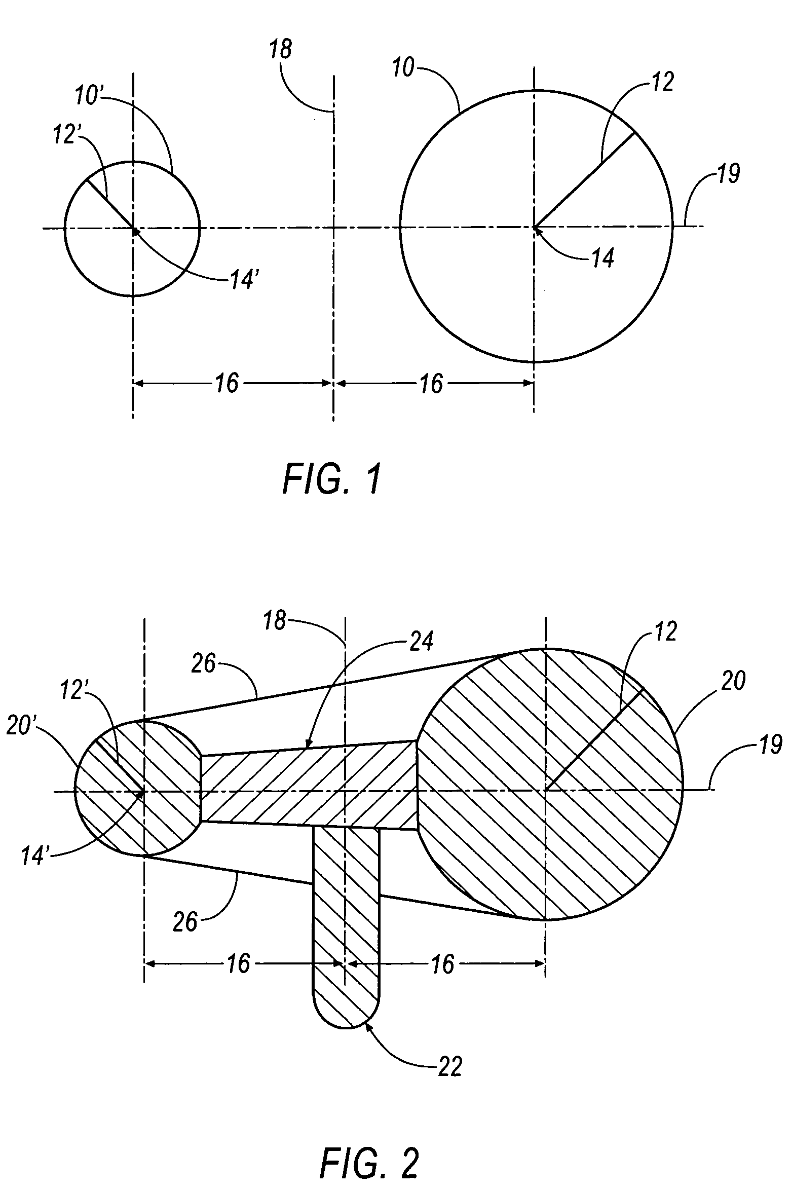
[0030] Referring to FIG. 1, a schematic representation of a cam surface 10, 10′ is shown according to an embodiment of the present invention. The surface 10, 10′ of the cam is defined by a radius 12, 12′ rotated about a central surface point 14, 14′, which is shown as being two different points in FIG. 1 but is actually a ring having a radius 16. In this regard, central surface point 14, 14′ is displaced at a fixed distan...


PUM


Abstract

An adjustable cam and follower system for a surgical device that includes a tri-dimensional rotatable cam member having a rotational input and a cam surface, the contour of which is defined by at least one radius of varying length. The system further includes a follower selectively moveable linearly, the follower configurable to ride substantially upon the cam surface as the cam rotates. A handpiece having an ergonomic member attachable thereto is also disclosed.

Description

CROSS REFERENCE TO RELATED APPLICATION [0001] This application claims priority to U.S. provisional application 60 / 580,068 filed on Jun. 16, 2004 and U.S. provisional application 60 / 503,056 filed on Sep. 15, 2003, both of which are incorporated herein by reference in their entirety.BACKGROUND OF THE INVENTION [0002] 1. Field of the Invention [0003] The present invention generally relates to the field of surgical cutting instruments and, more particularly, to surgical instruments having a selectively adjustable reciprocating cutter. [0004] 2. Description of the Related Art [0005] Cam systems are often used in machines to convert rotary motion into linear motion. One type of cam system uses a rotating cam to linearly drive a follower. In a particular implementation, the follower is held in constant contact with a surface of the cam by a biasing force, typically applied by a spring or an air cylinder. The shape of the rotating cam is generally configured to control the linear motion of ...

Claims


Application Information

Patent Timeline
Patent Type & Authority Applications(United States)
IPC IPC(8): A61B17/00A61B17/14A61B17/16A61B17/28A61B17/32A61C1/10A61C1/12
CPCA61B17/14A61B17/1604A61B17/1624A61B17/2909A61B17/32002A61B2017/00424A61B17/148A61B2017/2927A61B2017/320028A61B2017/320032A61C1/10A61C1/12A61B2017/00544A61B17/144
Inventor HOFMANN, RONALD L.DAVIGNON, ROBERT W.
Owner SUROS SURGICAL SYST
Why Eureka
Try Eureka