Video security system

a security system and video technology, applied in the field of video security systems, can solve the problems of overwriting a part of the video picture, laborious and tedious for the person operating the ptz camera, and inconvenient, so as to reduce the amount of momentum change, accurately control the movement of the platform, and improve the accuracy of the position determination

Inactive Publication Date: 2005-04-21
RHODES SCOTT ANTHONY +1
View PDF1 Cites 23 Cited by
  • Summary
  • Abstract
  • Description
  • Claims
  • Application Information

AI Technical Summary

Benefits of technology

[0065] a camera position control system for recording the location of a plurality of viewing positions and for controlling the movement of the platform between said viewing positions, the camera position control system being configured control the movement of the platform so as to provide a minimum period during which there is substantially zero acceleration between changes in acceleration of the platform from acceleration to deceleration so as to reduce the amount of...

Problems solved by technology

A disadvantage of such prior art systems is that the information is introduced into the video part of the video signal and hence over-writes a part of the video picture which would have otherwise been recorded.
This is quite laborious and tedious for the person operating the PTZ camera since it involves adjusting the pan, tilt, zoom and focus setting for the PTZ camera.
This is particularly inconvenient in a viewing region such as in a casino where there are many potential targets, where there is a requirement to quickly and reliably set viewing locations and where it is critical to be able to switch between typically two targets.
“Signal Equalisation”—Prior art video security systems have the problem that equalisation of the video signals must be provided for each video camera.
“Rotation End Stops”—Another problem of existing video security systems is that most of the cameras which they use are only able to rotate through about 360°.
“Pan Speed vs Zoom”—Prior art vide cameras have the further problem that when the lens is zoomed in (that is viewing an object at a distance) the rate of pan per degree of arc is the same as when the lens is zoomed ...

Method used


Image

  • Video security system
  • Video security system
  • Video security system

Examples


Embodiment Construction

)

Video Security System

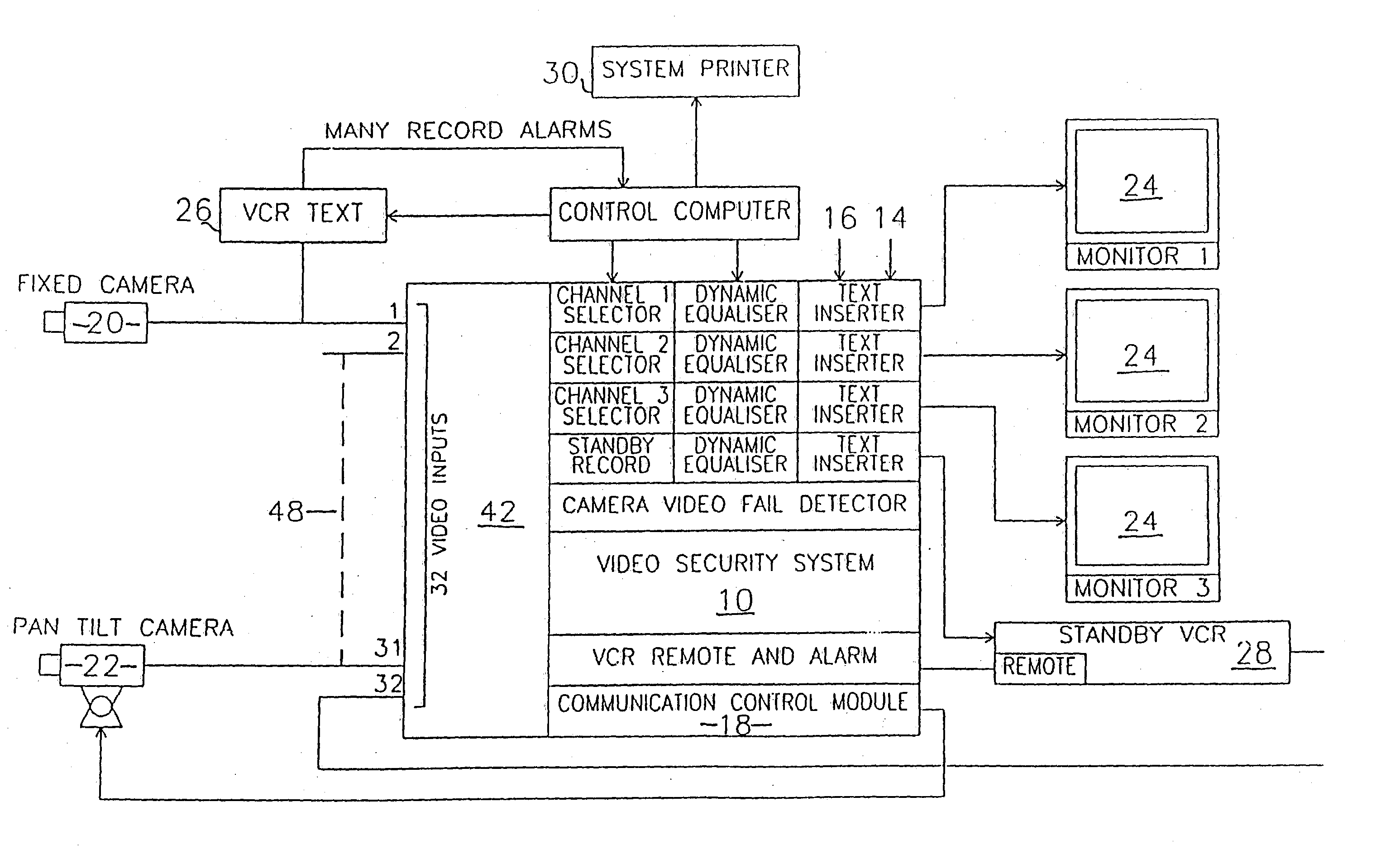
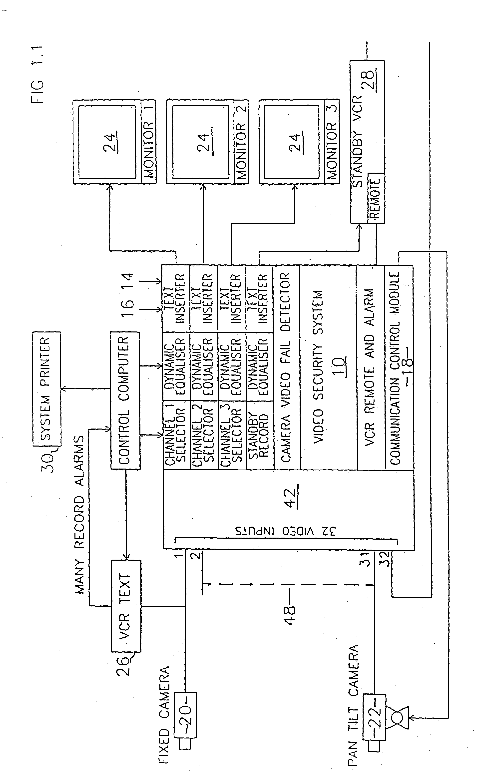
[0086] In FIG. 1 there is shown a Video Security System (VSS) 10 comprising an Automatic VCR Management System (AVCRMS) 12, a Text Insertion System (TIS) 14, a Transmission Cable Equalisation System (TCES) 16 and a Video Camera Substitution System (VCSS) 18.

[0087] The VSS 10 also comprises a plurality of fixed position cameras 20, a plurality of pan-tilt cameras 22, a plurality of video monitors 24, a plurality of VCRs 26, one or more standby VCRs 28 and a printer 30.

[0088] Typically, the VSS 10 is embodied in a computer system programmed to effect various routines equivalent to the systems 12, 14, 16 and 18 described herein.

Automatic VCR Management System

[0089] As shown in FIG. 2 the AVCRMS 12 comprises a controller 40 and a selector 42.

[0090] Typically the controller 40 is in the form of a computer programmed to effect certain control functions as described herein. The controller 40 is connected to a remote control input 44 of each of the plurality of V...


PUM


Abstract

The invention provides a video security system for monitoring a plurality of locations simultaneously. In one embodiment, the system includes a text insertion means connected between a video camera and monitor, a control means connected to the text insertion means, and a playback means operatively associated with the text insertion means and control means. Other embodiments include a video camera substitution system having a fixed video camera and a pan-tilt video camera and a video recorder substitution system having a plurality of alternate VRDs. In another embodiment, the system includes a programmable equalizer having a plurality of video input devices, a video output receiver, a switch connected between the input devices and receiver, a variable equalizer connected between the switch and receiver, and a controller storing line loss parameters for each input device, thereby providing equalization among a plurality of video cameras, monitors, and video signal recording devices.

Description

FIELD OF THE INVENTION [0001] The present invention relates to a video security system particularly, although not exclusively, envisaged for use in the monitoring of a plurality of locations, such as, in a building, for example, a casino. [0002] More particularly the present invention relates to a video security system (VSS) particularly directed at addressing the difficulties which prior art security systems generally experience, such as: [0003] 1. avoiding text information obliterating important video information; [0004] 2. switching repeatedly between two or more views of interest with a single camera; [0005] 3. dealing with equalisation problems between video cameras, video monitors and / or VCRs or other video signal recording device; [0006] 4. overcoming the problem of tracking an object with a camera when it approaches a 360° endstop; [0007] 5. overcoming the problem of pan / tilt camera control when zoomed out; [0008] 6. controlling the camera to move rapidly between two or more...

Claims


Application Information

Patent Timeline
IPC IPC(8): G08B13/14G08B13/196G08B15/00H04N5/232H04N5/765H04N5/77H04N5/775H04N5/92H04N7/08H04N7/084H04N7/10H04N7/18H04N19/89
CPCG08B13/19619H04N7/181G08B13/19643G08B13/19669G08B13/19671H04N5/232H04N5/23203H04N5/765H04N5/77H04N5/775H04N5/9206H04N7/08H04N7/084H04N7/102G08B13/1963H04N23/66H04N23/661H04N23/695
Inventor RHODES, SCOTT ANTHONYJACKSON, ANDREW WILLIAM
Owner RHODES SCOTT ANTHONY
Why Eureka
Try Eureka