Apparatus for separating particles from a flowing medium

a technology of fluid medium and apparatus, applied in the field of apparatus and method for separating solid particles and liquids, can solve the problems of high manufacturing cost and achieve the effects of reducing flow resistance, increasing pressure recovery, and reducing flow resistan

Active Publication Date: 2005-04-28
MANN HUMMEL GMBH
View PDF14 Cites 6 Cited by
  • Summary
  • Abstract
  • Description
  • Claims
  • Application Information

AI Technical Summary

Benefits of technology

[0018] In a further advantageous embodiment of the invention, the upstream end of the core of the outlet guide device has a rounded or spherical construction, so that an advantageous reduction in the flow resistance is achieved.
[0019] In accordance with yet another advantageous embodiment of the invention, the downstream end of the core has a tapered or conical configuration. The conical termination advantageously acts as a diffuser and thereby increases the pressure recovery, as a result of which the flow resistance is reduced.
[0020] A further manufacturing advantage is achieved by configuring the overall housing and one guide device without any undercuts, so that only the oppositely directed second guide device needs to be subsequently attached. Due to the absence of undercuts, the housing and one guide device can be produced together in one piece by an original forming process, especially by injection molding from a polymer or from a light metal. The advantage of this configuration is that it makes it possible to use very economical production methods as well as integrating different functional elements in a single, one-piece component.
[0021] For optimal adaptation of the apparatus, it is advantageous if the ratio of the diameter of the core of the outlet guide device to the diameter of the housing is from 0.4 to 0.8. The smallest possible pressure loss is achie...

Problems solved by technology

A disadvantageous aspect of this apparatus is its high manufacturing cost, ...

Method used


Image

  • Apparatus for separating particles from a flowing medium
  • Apparatus for separating particles from a flowing medium

Examples


Embodiment Construction

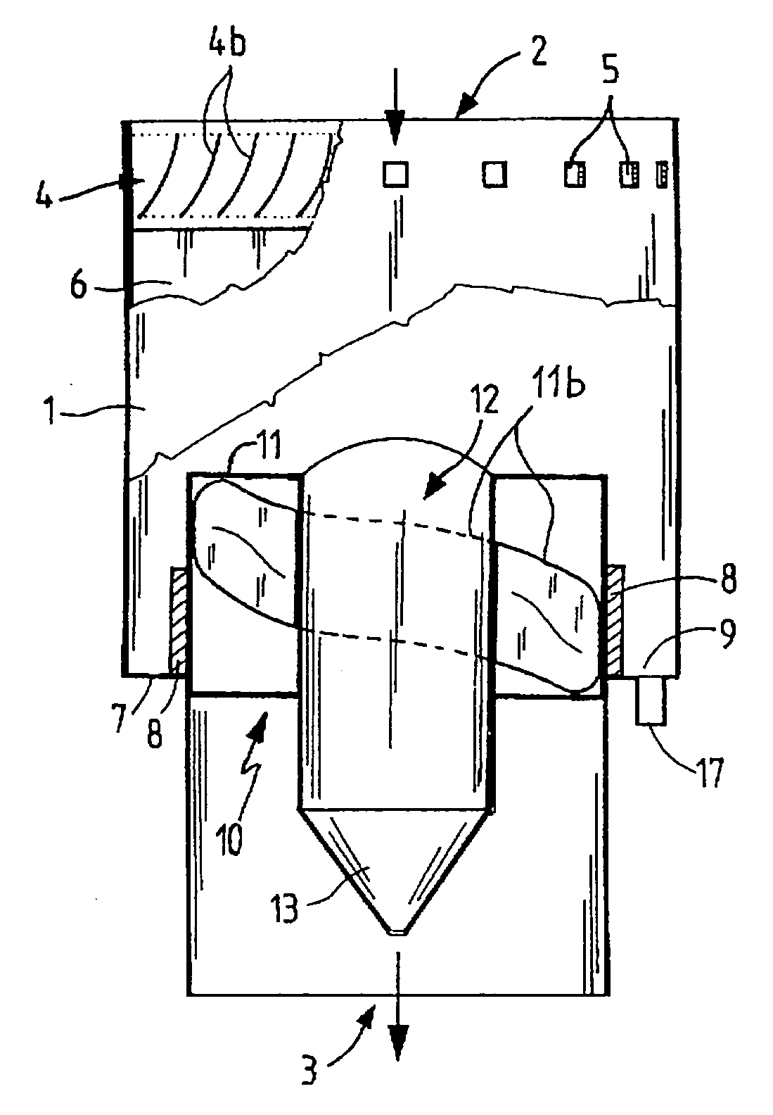
[0028]FIG. 1 shows a preferably hollow cylindrical housing 1 provided with an inlet 2 and an outlet 3. Furthermore, an inlet guide device 4 is clipped into recesses 5 in the housing 1. Separated particles are deposited at the housing wall in a separating zone 6. The separated particles are collected on a collecting base 7, which is disposed beneath the separating zone 6. A divider or separating element 8 prevents the separated particles from being re-entrained by the flowing air and, together with the collecting base 7, forms a collecting chamber 9. A discharge pipe 17 is arranged in the collecting base 7 and forms a connection for controlled discharge of the separated particles. An outlet guide device 10 comprises guide elements 11 and a cylindrical core 12. Outlet guide 10 is manufactured in one piece with the divider 8, the collecting base 7 and the housing 1.

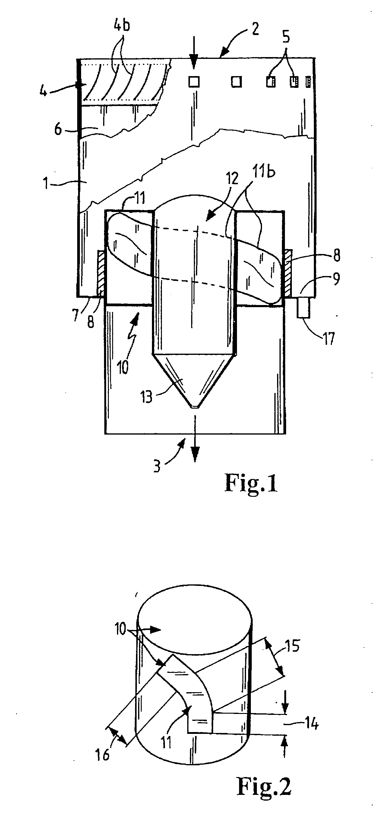
[0029] In the drawing, the external contour of the guide elements 11 has a rectangular cross-section. The helical lines 1...


PUM

PropertyMeasurementUnit
Pressureaaaaaaaaaa
Angleaaaaaaaaaa
Flow rateaaaaaaaaaa

Abstract

A separating apparatus which enables particles to be separated from a flowing medium by a preliminary separator which avoids the undesirably high pressure losses due to the flow resistance of known preliminary separators. The separating apparatus has a housing with an inlet and an outlet, in which a flow of air at the inlet end is caused to rotate by an inlet guide device, and is redirected again at the outlet end by an outlet guide device into a linear flow. The pressure recovery is achieved by a defined curvature and arrangement of the guide elements. The guide element curvature has an inlet contour, a retarding contour and a stabilizing contour. Preliminary separators of this type are used primarily in the air intake tracts of internal combustion engines exposed to heavy contamination, such as engines in farm machinery or construction machinery.

Description

BACKGROUND OF THE INVENTION [0001] The invention relates to an apparatus and method for separating solid particles and liquids from flowing gases. [0002] Separators of this type are used predominantly in the intake air of internal combustion engines if increased contamination and / or the presence of liquid droplets are generally expected as, for example, in engines for farm machinery and construction machinery of all types, as well as in commercial vehicles. Usually, these devices are used as preliminary separators. [0003] U.S. Pat. No. 3,064,411 discloses an apparatus which is intended to separate solids from a fluid medium and has the following characteristics. The cylindrical housing of the device tapers conically at its axial end faces, and the inlet and the outlet are disposed at the reduced diameters. An inlet guide vane is arranged on the inlet side and an outlet guide vane at the outlet side within the cylinder, which is tapered conically at both ends. Both guide devices are ...

Claims


Application Information

Patent Timeline
IPC IPC(8): B01D45/16B04C3/06F02M35/022
CPCB01D45/16F02M35/022B04C2003/006B04C3/06Y02A50/2351
Inventor GREIF, VOLKERHAEHN, JENS
Owner MANN HUMMEL GMBH
Why Eureka
Try Eureka