System and method for interpreting drilling data

a technology of drilling data and system, applied in the field of drilling wellbore through the earth, can solve the problems of increasing monotonically, substantial amount of time, and incurring exposure to drilling hazards, and the depth of the wellbore is not monotonically increasing

Inactive Publication Date: 2005-04-28
HUTCHINSON MARK W
View PDF9 Cites 66 Cited by
  • Summary
  • Abstract
  • Description
  • Claims
  • Application Information

AI Technical Summary

Problems solved by technology

As is well known in the art, however, a substantial amount of the time during drilling operations the depth of the wellbore is not, in fact, increasing monotonically, but may include operations in which the drill string, for example, is removed from the wellbore, is moved up and down repeatedly, or remains in a fixed axial position while it is rotated and the drilling fluid is circulated.
The rig operations which do not result in monotonically increasing depth with respect to time may incur exposure to drilling hazards such as stuck pipe, blowout or lost drilling fluid (“lost circulation”).
Drilling data reco...

Method used


Image

  • System and method for interpreting drilling data
  • System and method for interpreting drilling data
  • System and method for interpreting drilling data

Examples


Embodiment Construction

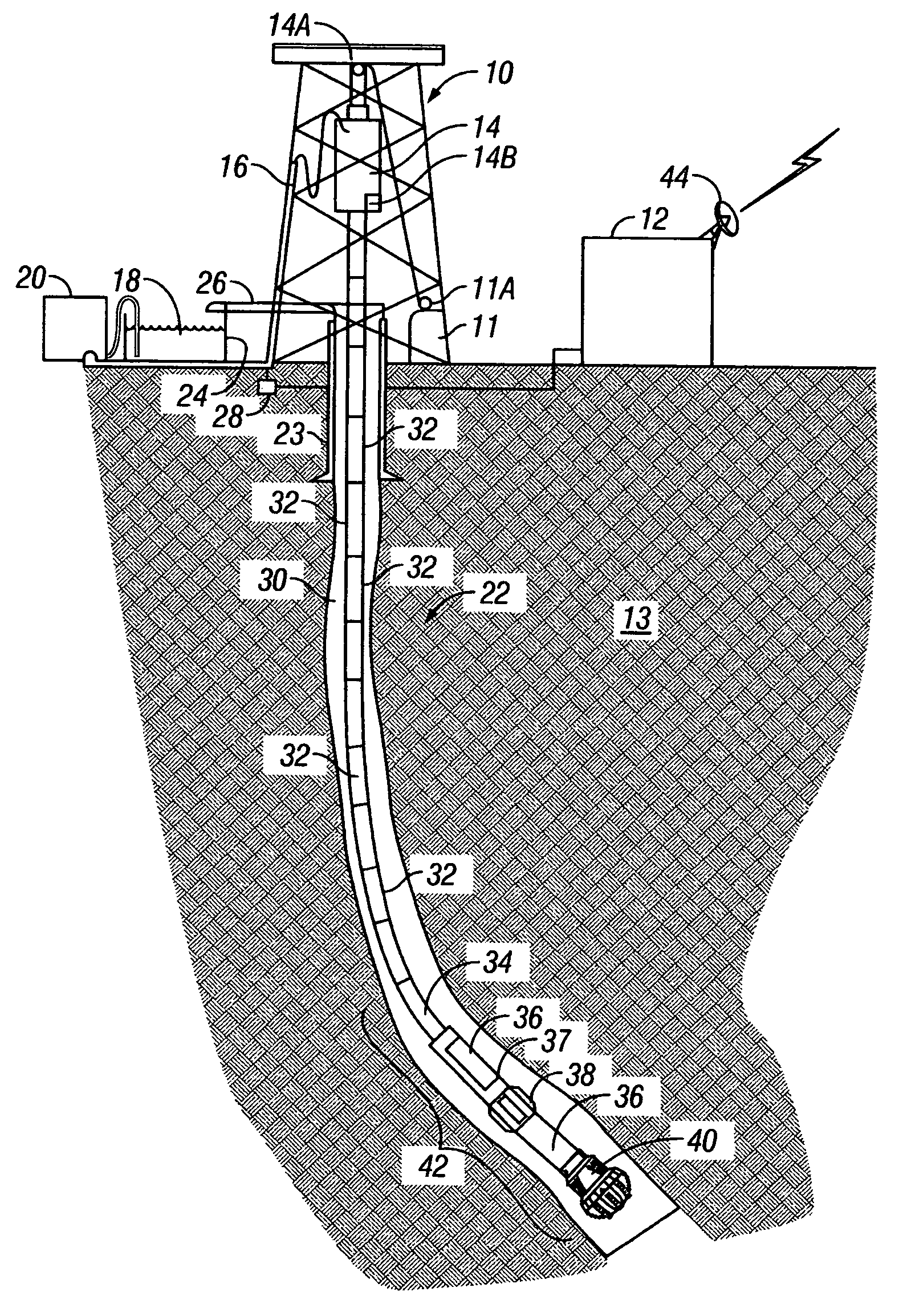
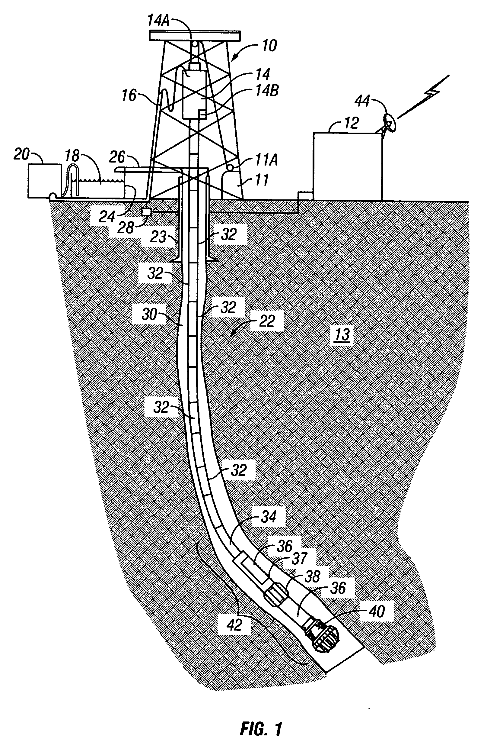
[0029]FIG. 1 shows a typical wellbore drilling system which may be used with various embodiments of a method according to the invention. A drilling rig 10 includes a drawworks 11 or similar lifting device known in the art to raise, suspend and lower a drill string. The drill string includes a number of threadedly coupled sections of drill pipe, shown generally at 32. A lowermost part of the drill string is known as a bottom hole assembly (“BHA”) 42, which includes at its lowermost end in the embodiment of FIG. 1, a drill bit 40 to cut through earth formations 13 below the earth's surface. The BHA 42 may include various devices such as heavy weight drill pipe 34, and drill collars 36. The BHA 42 may also include one or more stabilizers 38 that include blades thereon adapted to keep the BHA approximately in the center of the wellbore 22 during drilling. In various embodiments of a drilling system, one or more of the drill collars 36 may include a measurement while drilling (MWD) senso...


PUM


Abstract

A method is disclosed for identifying potential drilling hazards in a wellbore, including measuring a drilling parameter, correlating the parameter to depth in the wellbore at which selected components of a drill string pass, determining changes in the parameter each time the selected components pass selected depths in the wellbore, and generating a warning signal in response to the determined changes in the parameter. Another disclosed method includes determining times at which a drilling system is conditioning the wellbore, measuring torque, hookload and drilling fluid pressure during conditioning, and generating a warning signal if one or more of maximum value of measured torque, torque variation, maximum value of drill string acceleration, maximum value of hookload and maximum value of drilling fluid pressure exceeds a selected threshold during reaming up motion of the drilling system.

Description

CROSS-REFERENCE TO RELATED APPLICATIONS [0001] This is a continuation of International Patent Application No. PCT / US03 / 10280 filed on Apr. 3, 2003. Priority is claimed from U.S. Provisional Application No. 60 / 374,117 filed on Apr. 19, 2002.STATEMENT REGARDING FEDERALLY SPONSORED RESEARCH OR DEVELOPMENT [0002] Not applicable. BACKGROUND OF THE INVENTION [0003] 1. Field of the Invention [0004] This invention relates generally to the field of drilling wellbores through the earth. More specifically, the invention relates to systems and methods for acquiring data related to wellbore drilling, characterizing the data according to the particular aspect of drilling being performed during acquisition, and determining the possibility of encountering particular drilling hazards by analyzing the data thus characterized. [0005] 2. Background Art [0006] Drilling wellbores through the earth includes “rotary” drilling, in which a drilling rig or similar lifting device suspends a drill string. The d...

Claims


Application Information

Patent Timeline
IPC IPC(8): E21B36/04E21B41/00E21B44/00E21B47/04E21B49/00
CPCE21B44/00E21B49/003E21B47/04
Inventor HUTCHINSON, MARK W.
Owner HUTCHINSON MARK W
Why Eureka
Try Eureka