
Downhole telemetry system and method

a telemetry system and downhole technology, applied in the field of drill string telemetry, can solve problems such as reliability problems and failure of the entire telemetry system

Active Publication Date: 2005-04-28
SCHLUMBERGER TECH CORP
View PDF29 Cites 183 Cited by
  • Summary
  • Abstract
  • Description
  • Claims
  • Application Information

AI Technical Summary

Benefits of technology

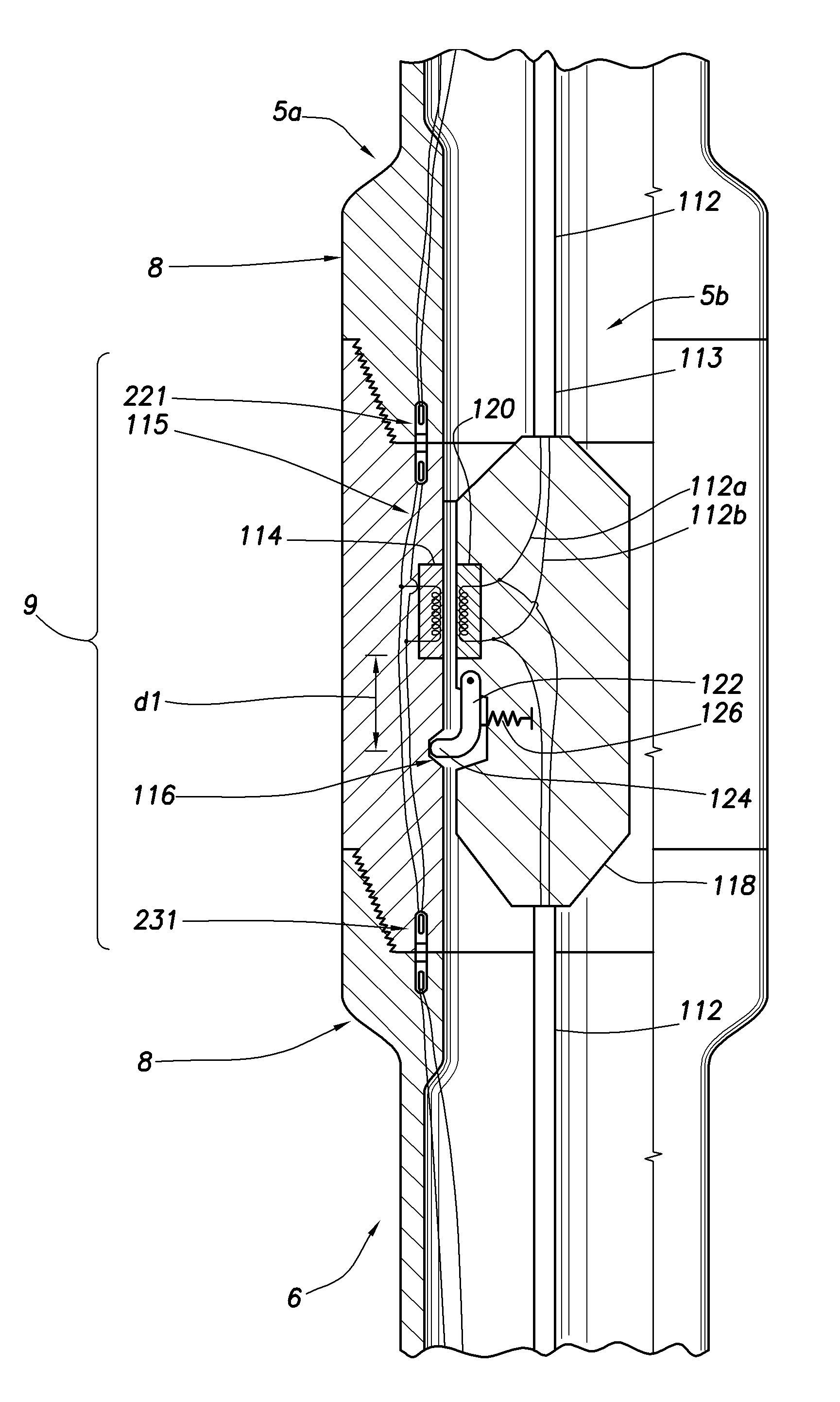
[0024] The inventive cabled communication link may be applied to advantage in a drill string wherein a plurality of WDP joints are interconnected within the drill string between the two adapter subs to form a piped communication link. In this application, the cabled communication link establishes an alternative pathway to the piped communication link for transmitting a signal through the drill string, whereby a failure in the piped communication system (i.e., the WDP system) may be bypassed.
[0025] The

Problems solved by technology

The sheer number of connections in a drill string raises concerns of reliability for a WDP system.
If one of the wired connections in a WDP system fails, then that communication link fails, whereby the entire telemetry system fails.

Method used


Image

  • Downhole telemetry system and method
  • Downhole telemetry system and method
  • Downhole telemetry system and method

Examples


Embodiment Construction

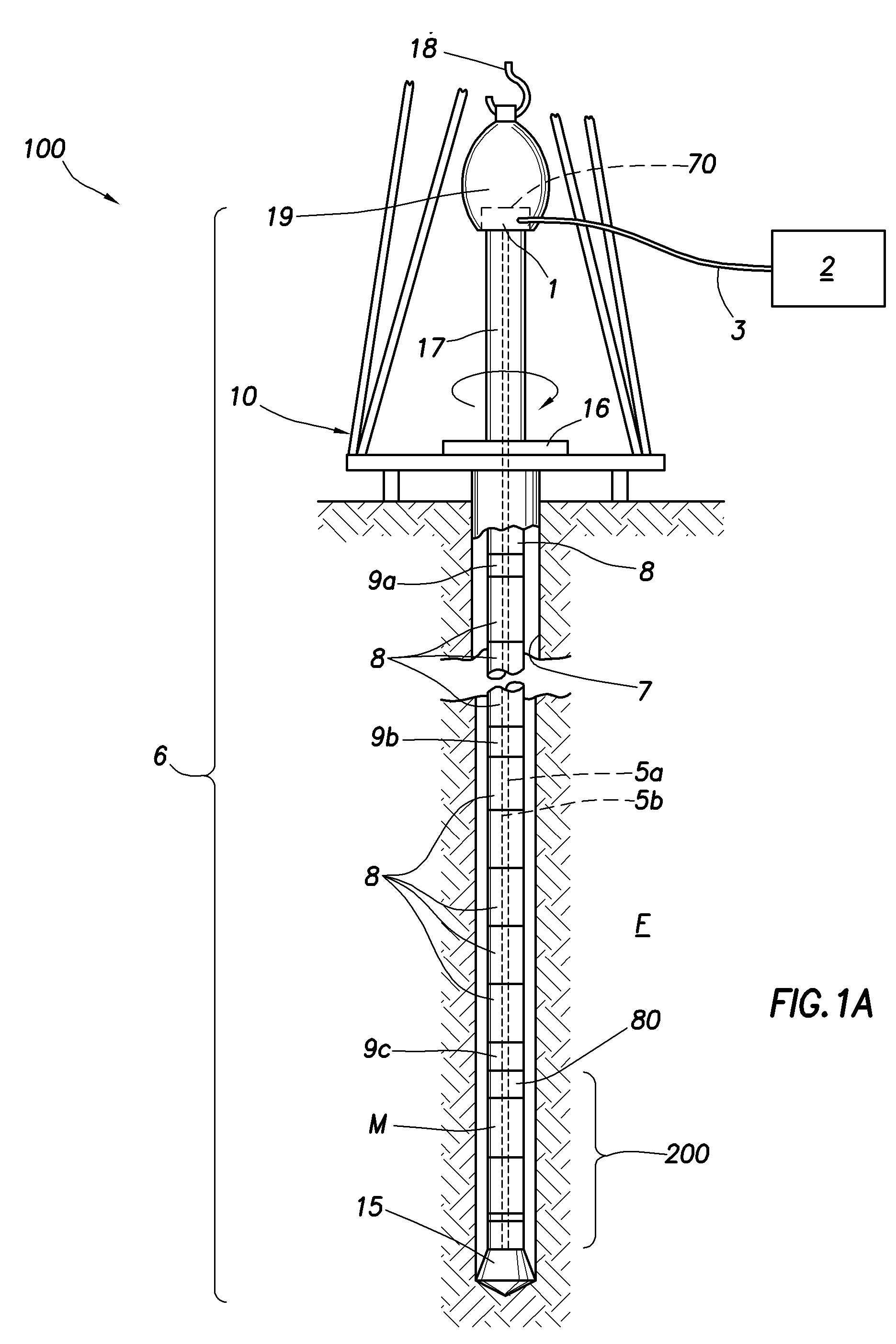
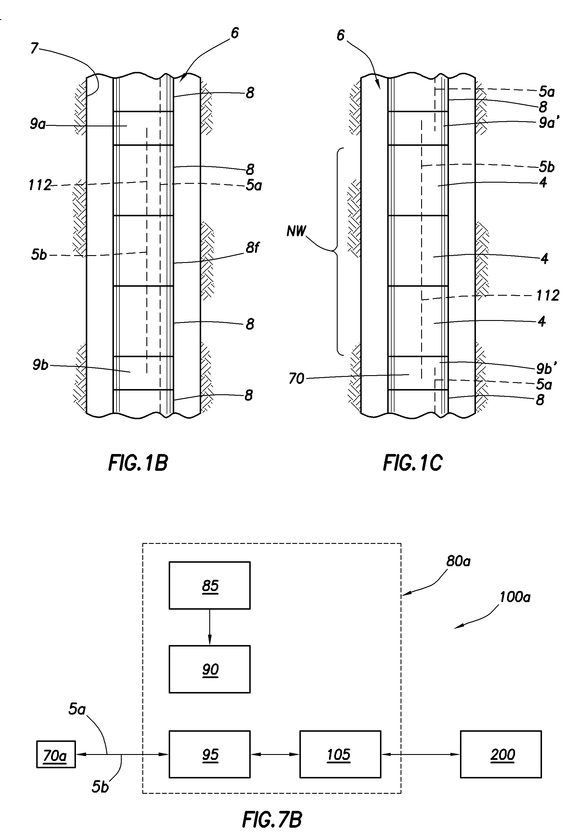
[0063]FIG. 1A depicts a drill string 6 that employs a telemetry system 100 in accordance with one aspect of the present invention. The drill string 6 includes a plurality of interconnected tubular members (described further below) suspended from a derrick and platform assembly 10 by way of a traveling block (not shown) and a hook 18. The upper end of the drill string 6 is defined by a kelly joint 17, the uppermost tubular member in the string, which is engaged by a conventional torque-applying means including a rotary table 16 for rotating the kelly joint as well as the entire drill string 6. A swivel 19 connects the hook 18 to the kelly joint 17, and permits rotation of the kelly joint and the drill string 6 relative to the hook.

[0064] The lower end of the drill string is defined by a drill bit 15 which drills through the formation F to create a wellbore 7. The drill bit is connected for rotation with the drill string 6 in a rotary drilling configuration of the sort described abov...


PUM


Abstract

A cabled communication link for a drill string includes spaced apart adapter subs within the drill string and a cable connecting the adapter subs for communication of a signal therebetween. The cabled communication link may be drill pipe joints are interconnected within the drill string between adapter subs to form a piped communication link, whereby the cabled communication link establishes a pathway to the piped communication link for transmitting a signal through the drill string. The cabled communication link may also be in a non-wired section of the drill string is disposed between adapter subs, whereby the cabled communication link establishes a pathway for transmitting a signal through the non-wired section of the drill string. Inductive couplings are preferably used for communication across the adapter subs and wired drill pipe joints. Another aspect of the cabled communication employs wireless transceivers at or near the surface of the wellbore.

Description

CROSS REFERENCE TO RELATED APPLICATIONS [0001] This application is related to copending U.S. patent application Ser. No. 10 / 160,311 filed on May 31, 2003, which claims priority to U.S. patent application Ser. No. 09 / 881,333 filed on Jun. 14, 2001, which in turn claims priority to U.S. Provisional Patent Application Ser. No. 60 / 278,090 filed on Mar. 23, 2001.BACKGROUND OF INVENTION [0002] 1. Field of the Invention [0003] The present invention relates generally to drill string telemetry. More specifically, the invention relates to wired drill pipe telemetry systems and techniques for transmitting signals through a drillstring. [0004] 2. Related Art [0005] Downhole systems, such as Measurement While Drilling (MWD) and Logging While Drilling (LWD) systems, derive much of their value from their abilities to provide real-time information about borehole conditions and / or sub-surface formation properties. These downhole measurements may be used to make decisions during the drilling process ...

Claims


Application Information

Patent Timeline
IPC IPC(8): E21B47/12E21B17/02E21B47/00
CPCE21B17/023E21B47/122E21B47/12E21B17/028E21B47/13E21B17/0283
Inventor BOYLE, BRUCE W.PACAULT, NICOLASHACHE, JEAN-MICHELHUTIN, REMIMADHAVAN, RAGHUJUNDT, JACQUES
Owner SCHLUMBERGER TECH CORP
Learn More