Moisture sensor sprinkler control systems

a technology of moisture sensor and sprinkler control, which is applied in the direction of automatic control, ignition, instruments, etc., can solve the problems of waste of water, poor performance, and inefficiency

Inactive Publication Date: 2005-04-28
BOWERS JOHN R +1
View PDF25 Cites 38 Cited by
  • Summary
  • Abstract
  • Description
  • Claims
  • Application Information

AI Technical Summary

Problems solved by technology

Considerable inefficiency and poor performance can result when using pre-programmed watering controls as described above.
For example, such watering systems typically irrigate during rain storms, thus resulting in wasted water.
This results in particular zones within a multi-zone system which are inadequately watered, while other zones are watered to excess, thus producing dry areas, waterlogged areas, water wastage and derogatory effects on the grass or other crop being irrigated.
However, the differences which are satisfactory during one season or weather period may not be satisfactory during a different season or weather period.
Also, daily temperature and other daily or episodal weather fluctuations may not be adequately compensated for using watering time periods set under prior conditions and previously observed results.
Attempting to eliminate such problems under a pre-programmed, time-based watering scheme requires tedious, trial and error adjustments to the irrigation controller.
These adjustments typically deliver results which are an attempt to provide proper control for the circumstances just experienced, but are not satisfactory under current changes and variable future conditions.
For example, one set of adjustments made during mild weather may yield undesirable results during hotter, dryer weather conditions which may begin the day after an adjustment has

Method used


Image

  • Moisture sensor sprinkler control systems
  • Moisture sensor sprinkler control systems
  • Moisture sensor sprinkler control systems

Examples


embodiment

of FIG. 2

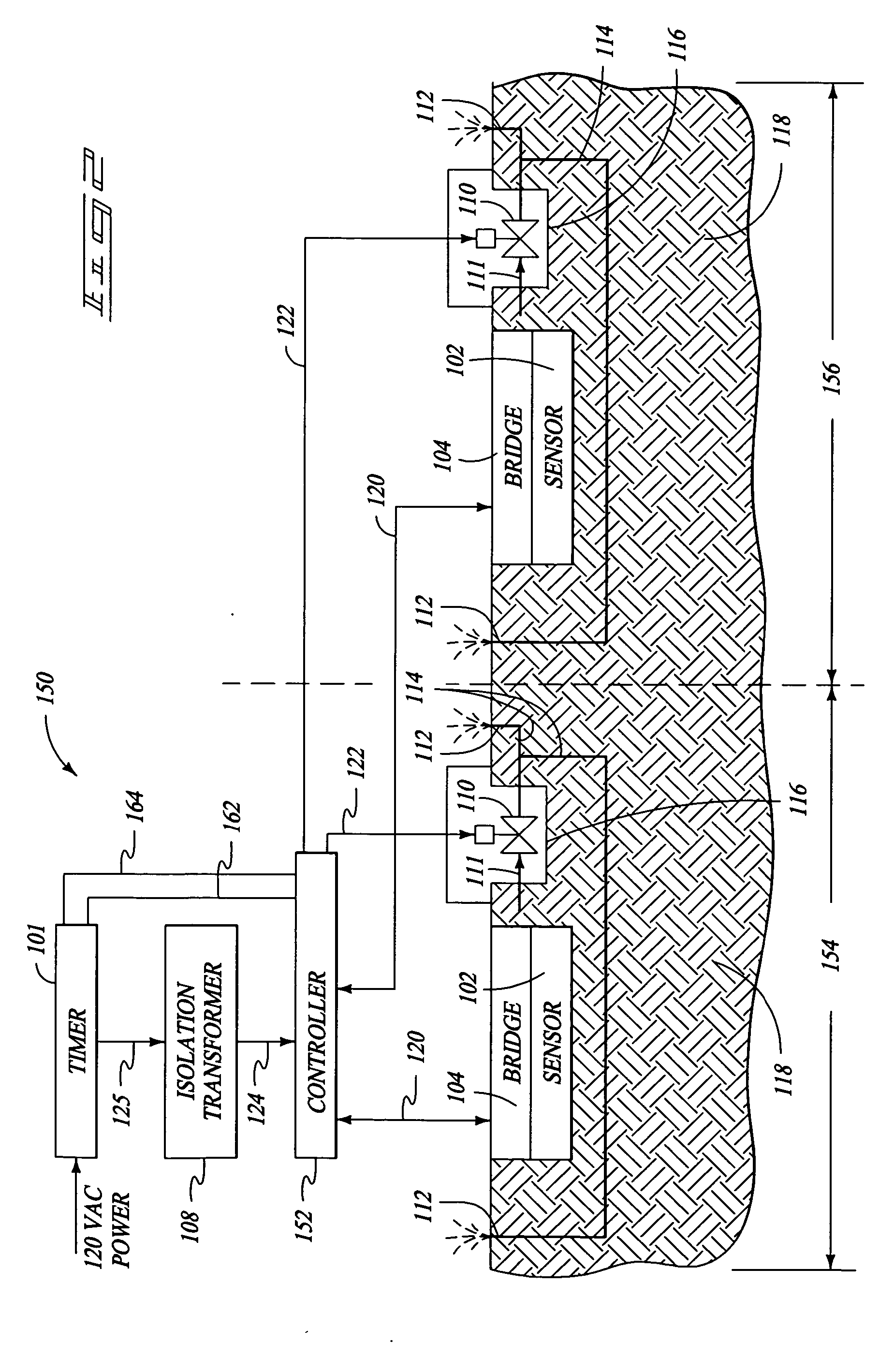
[0042]FIG. 2 is a block diagram of an irrigation control system 150 according to another embodiment of the invention. Irrigation system 150 includes a timer 101, an isolation transformer 108, and connections 124 and 125 operating similar to as described above for the embodiment of FIG. 1. However, connection 125 is preferably connected to the master valve control terminal of timer 101 and remains on during the entire watering cycle covering all zones.

[0043] Further included in system 150 is a controller 152 coupled to the connection 124 and receiving electrical power therefrom, as controlled by the master valve output signal of timer 101. Controller 152 is similar in operation to controller 106 described above. Controller 152 has multi-channel capability to independently sense and control two separate irrigation zones 154 and 156. This multi-zone capability is accommodated by zone output terminals which are separately communicated by conductors 162 and 164 to individual zo...


PUM


Abstract

Irrigation systems, moisture sensors and related methods having a sensor imbedded in the ground to sense moisture and help control watering. The sensor is responsive to capacitance changes from ground moisture variations. The sensor uses spaced insulated electrodes which are mounted within a granular filled chamber within a water-permeable shell. The sensor is mounted as part of a ground unit that also includes a high frequency driver that excites the sensor. The ground unit further has a detector circuit which produces a moisture indicating signal based on the capacitance which varies with ground moisture. Also disclosed are controllers that electrically isolate the ground units so that reliable moisture signals can be obtained and used to control irrigation. The controllers can be configured to provide multiple zone operation using a shared controller having shared or independent moisture adjusters.

Description

TECHNICAL FIELD [0001] The invention relates to irrigation sensing and control systems. In particular, the invention relates to systems and methods for sensing and controlling irrigation based upon improved ground moisture sensors and related circuitry and associated techniques. BACKGROUND OF THE INVENTION [0002] Irrigation control systems known in the art typically employ a time clock and controller coupled to one or more electrically actuated or activated valves. These systems typically use predetermined watering time periods which are set by programming of the irrigation controller. The programming of such controllers may include dial settings, digital control settings, placement of mechanical pegs or stops, or some other manipulation of the time clock or controller settings. [0003] When a predetermined watering start time occurs, one or more of the associated irrigation valves are opened. The irrigation valves are open for a pre-programmed watering period and then closed under t...

Claims


Application Information

Patent Timeline
IPC IPC(8): A01G25/16B05B12/08
CPCA01G25/167Y10T137/189
Inventor BOWERS, JOHN R.BOWERS, JOHN W.
Owner BOWERS JOHN R
Why Eureka
Try Eureka