Check patentability & draft patents in minutes with Patsnap Eureka AI!

Variable speed brushless DC motor

Inactive Publication Date: 2005-04-28
HSIEN LIN CHIU
View PDF2 Cites 2 Cited by
  • Summary
  • Abstract
  • Description
  • Claims
  • Application Information

AI Technical Summary

Benefits of technology

[0012] The present invention has been accomplished under the circumstances in view. It is therefore the main object of the present invention to provide a variable speed brushless DC motor, which uses a stator module to replace voltage drop power resistor, thereby lowering the manufacturing cost and minimizing the motor size. It is another object of the present invention to provide a variable speed brushless DC motor, which keeps the amount of electric current passing through the speed-change switch to be about one half of the total electric current of the stator module, so that the capacity of the speed-change switch can be greatly reduced to lower the manufacturing cost. To achieve these and other objects of the present invention, the variable speed brushless DC motor comprises a rotor, a commutation circuit, and a stator module. The commutation circuit comprises a power circuit and a signal circuit. The power circuit comprises a stator winding power source, four commutation switches, and a speed-change switch. The signal circuit comprises a rotor position sensor circuit and a commutation logic circuit. The commutation switches are arranged into two commutation switch sets connected in parallel to the stator winding power source. The speed-change switch is installed in one commutation switch set. The stator module is connected between the two commutation switch sets. The commutation logic circuit is adapted to connect and control on / off status of the four commutation switches of the power circuit. The stator module comprises at least two stator windings. On / off status of the speed-change switch controls supply of electric current to the stator module to further selectively energize the at least two stator windings.

Problems solved by technology

The use of a voltage drop power resistor A8 in the power circuit A greatly complicates the circuit and increases its size and manufacturing cost.
Because the operation of the voltage drop power resistor A8 in the power circuit A releases heat energy, a cooling fan using such a variable speed single-phase brushless DC motor has a low performance.

Method used


Image

  • Variable speed brushless DC motor
  • Variable speed brushless DC motor
  • Variable speed brushless DC motor

Examples


Embodiment Construction

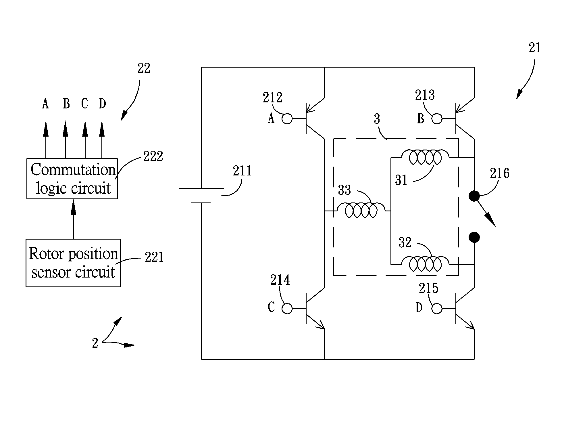
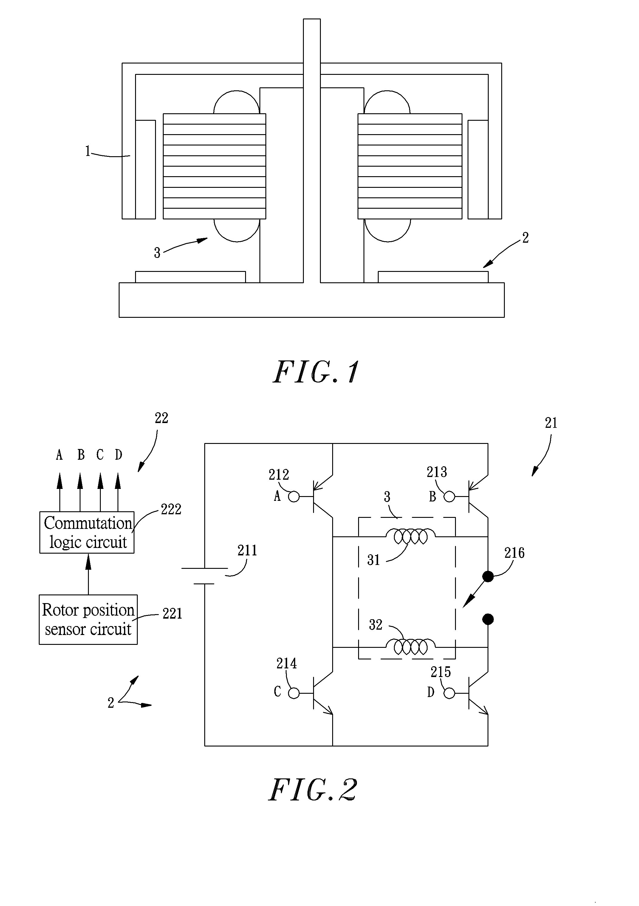
[0023] Referring to FIGS. 1 and 2, a variable speed brushless DC motor in accordance with the present invention is shown comprised of a rotor 1, a commutation circuit 2, and a stator module 3. The commutation circuit 2 comprises a power circuit 21 and a signal circuit 22. The power circuit 21 comprises a stator winding power source 211, a first commutation switch 212, a second commutation switch 213, a third commutation switch 214, and a fourth commutation switch 215, and a speed-change switch 216. The signal circuit 22 comprises a rotor position sensor circuit 221 and a commutation logic circuit 222. Further, the stator module 3 comprises a first stator winding 31 and a second stator winding 32. And the two stators windings 31 and 32 are the same phase.

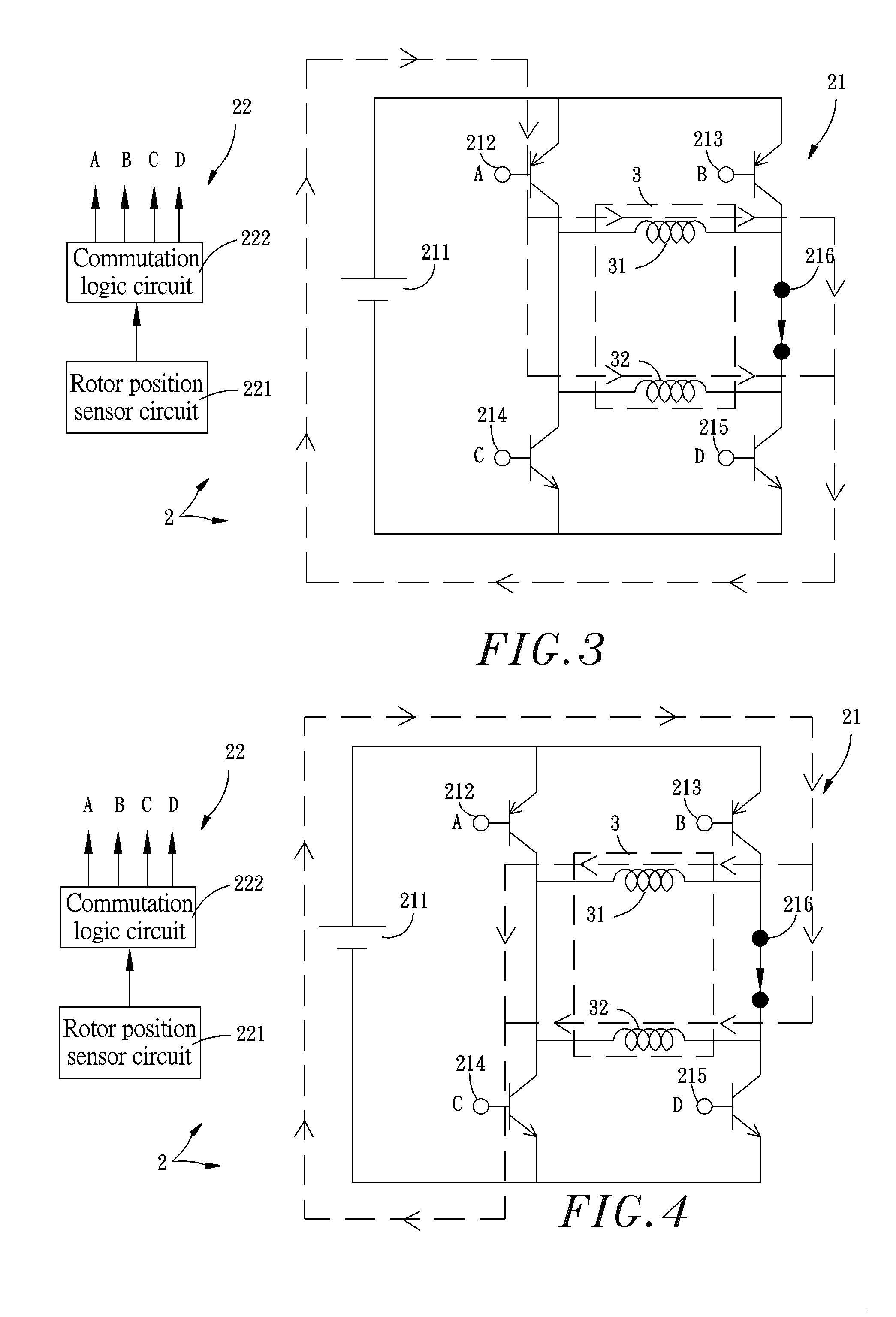
[0024] Referring to FIGS. 3 and 4, when the speed-change switch 216 of the power circuit 21 is on and the stator winding power source 211 is outputting a voltage, the rotor position sensor circuit 221 of the signal circuit 22 detect...


PUM


Abstract

A variable speed brushless DC motor includes a rotor, a stator module, and a commutation circuit having commutation switches and a speed-change switch. By means of on / off status of the speed-change switch to control the way of electric current passing through the stator module, the torque-rotational speed characteristic curve of the variable speed brushless DC motor is changed, and therefore the rotational speed of the motor is relatively changed.

Description

CROSS REFERENCE TO RELATED APPLICATIONS [0001] This application claims the priority benefit of Taiwan patent application number of 092210762 filed on Jun. 12, 2003. BACKGROUND OF INVENTION [0002] 1. Field of the Invention [0003] The present invention relates to a brushless DC motor and more particularly, to a variable speed brushless DC motor, which utilizes on / off status of a speed-change switch to control the way of electric current passing through the stator module, so as to further change the torque-rotational speed characteristic curve of the variable speed brushless DC motor, achieving the desired motor rotational speed control. [0004] 2. Description of the Related Art [0005] The history of AC motor is over one hundred years, however, the history of brushless DC motor has only several decades. Since mid 1980s, brushless DC motor has been intensively used in instruments. Because brushless DC motor can be made to fit the specifications of different information products, market g...

Claims


Application Information

Patent Timeline
IPC IPC(8): H02K13/00H02P6/08
CPCH02P6/08
Inventor CHIU, HSIEN-LIN
Owner HSIEN LIN CHIU
Features
  • R&D
  • Intellectual Property
  • Life Sciences
  • Materials
  • Tech Scout
  • Unparalleled Data Quality
  • Higher Quality Content
  • 60% Fewer Hallucinations
Learn More