Radio-wave propagation characteristic forecasting system and its method, and program

a radio wave propagation characteristic and forecasting system technology, applied in the direction of transmission monitoring, receiver monitoring, instruments, etc., can solve the problems of inability to accurately estimate the diffraction phenomenon, the possibility of ray colliding with the edge of the structure provided as a line is also very low, and the effect of reducing the probability of collision

Active Publication Date: 2005-04-28
NEC CORP
View PDF0 Cites 16 Cited by
  • Summary
  • Abstract
  • Description
  • Claims
  • Application Information

AI Technical Summary

Benefits of technology

[0020] It is an object of the present invention to provide a high-speed and high-accuracy radio-wave propagation characteristic forecasting system and its method and a program by correctly estimating a diffraction phenomenon and combining the phenomenon with the launching method when a ray passes the vicinity of an edge of a structure.
[0024] Functions of the present invention are described below. In the case of the ray launching method, a ray spread decided correspondingly to the radiation interval at a transmission point and the propagation distance from the transmission point is defined in each ray. However, the present invention makes the combination with the conventional launching method easy and realizes a high-speed and high-accuracy radio-wave propagation characteristic forecasting system by generating a diffracted wave with an edge when the distance between the edge and a ray is smaller than a ray spread radius even if the ray does not directly collide with the edge when the edge passes the vicinity of the edge.

Problems solved by technology

However, because a ray is a line defined in a three-dimensional space having an infinitesimal size, the possibility that the ray collides with an edge of the structure provided as a line is also very low.
Therefore, there is a problem that a diffraction phenomenon cannot correctly be estimated because diffracted waves are hardly generated only by simply applying the conventional UTD method to the ray launching method.

Method used


Image

  • Radio-wave propagation characteristic forecasting system and its method, and program
  • Radio-wave propagation characteristic forecasting system and its method, and program
  • Radio-wave propagation characteristic forecasting system and its method, and program

Examples


Embodiment Construction

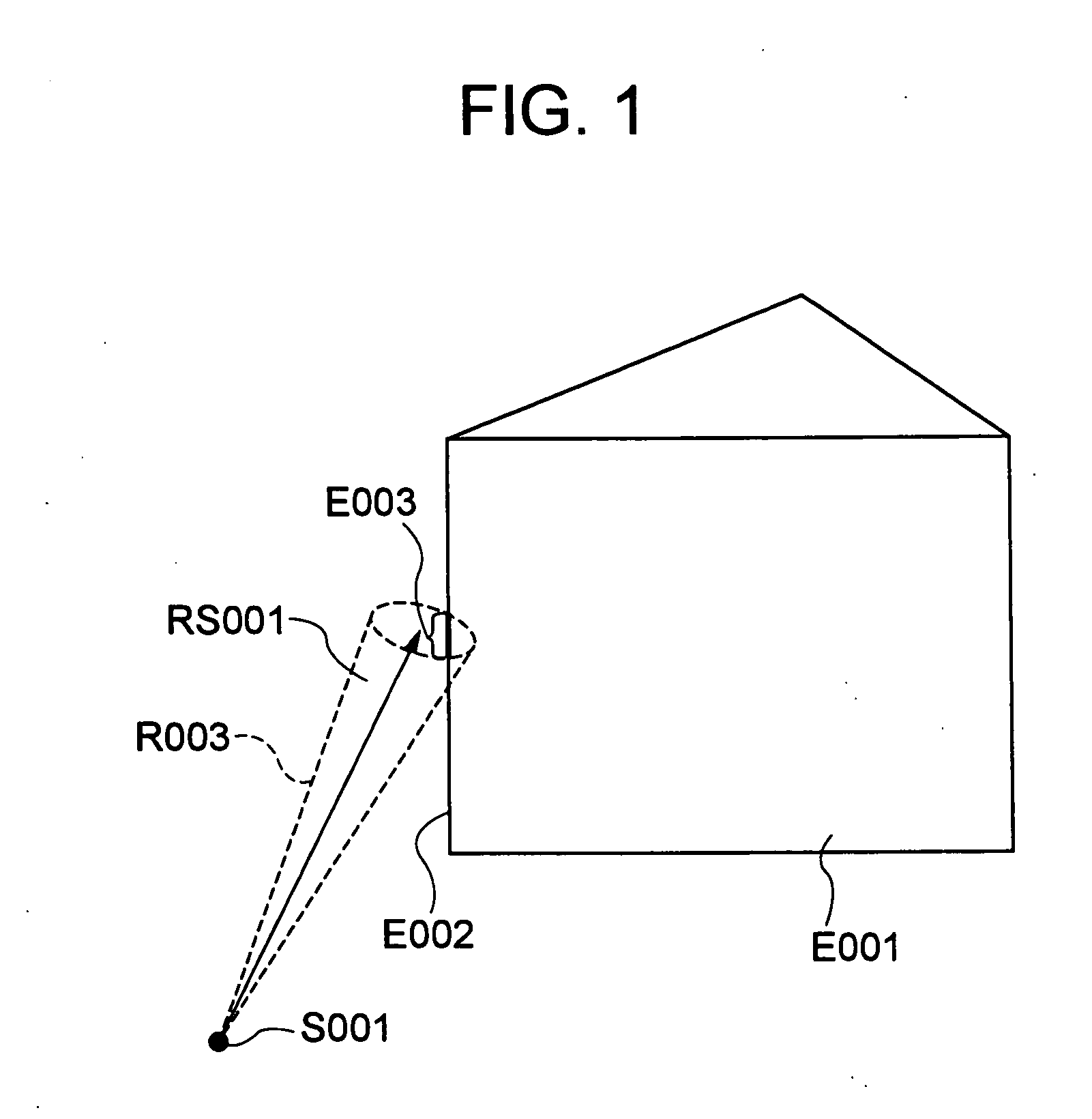
[0044] Embodiments of the present invention are described below in detail by referring to the accompanying drawings. FIG. 1 is an illustration showing a state when a diffracted ray is generated in an embodiment of the present invention. As shown in FIG. 1, a case is considered in which a ray R003 radiated from a transmission point S001 passes the vicinity of an edge E002 of a structure E001. In this case, a ray spread RS001 is defined for the ray R003 and the ray spread RS001 intersects the edge E002 at an interval E003.

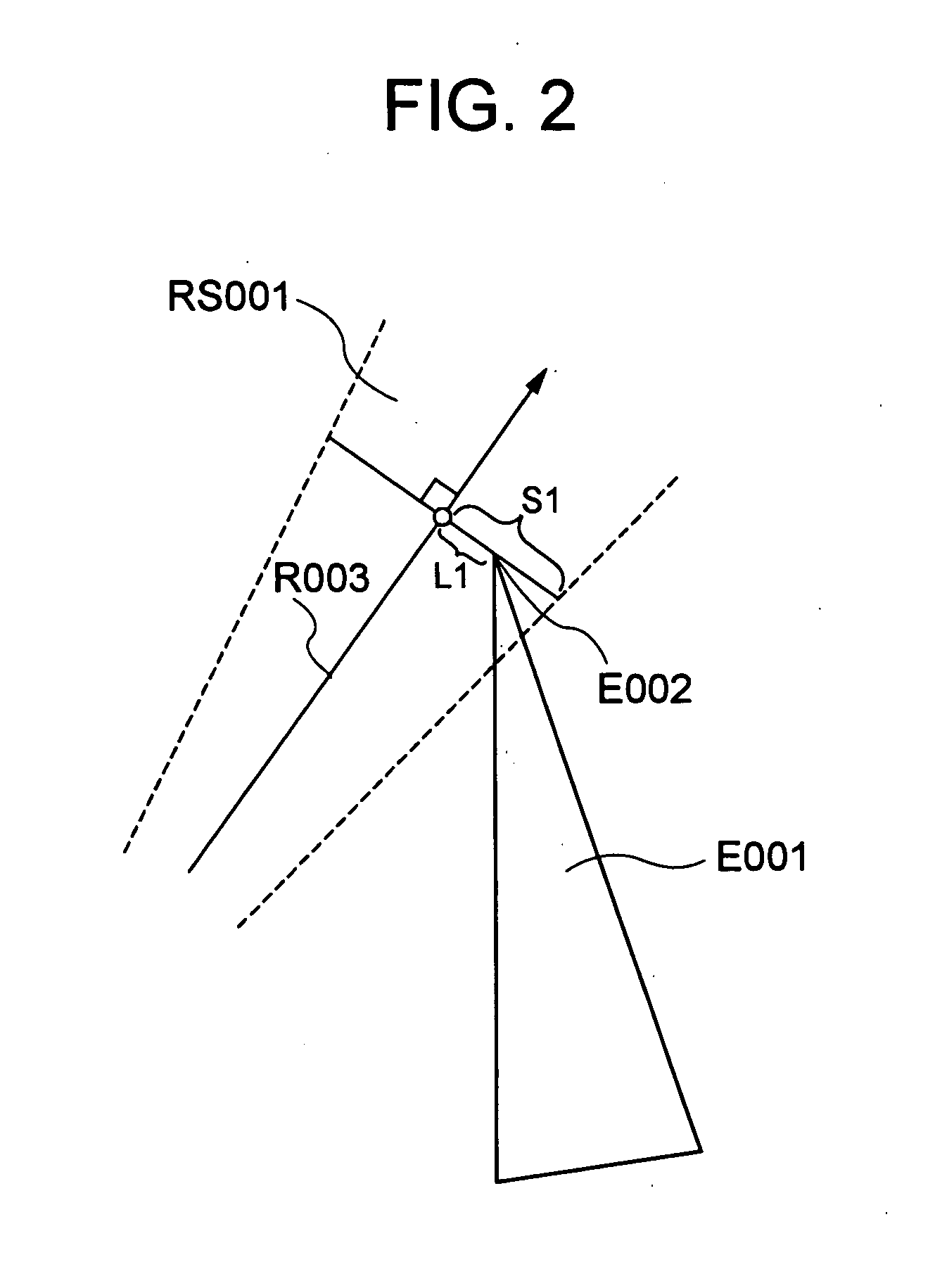
[0045]FIG. 2 is an illustration for explaining the intersection determination between the edge E002 and the ray spread RS001, which is a drawing when viewing FIG. 1 from the top. The intersection determination is performed by measuring the vertical distance L1 between the ray R003 and edge E002 and comparing the distance L1 with the spread radius S1 of the ray spread RS001 corresponding to the ray R003 at the spot concerned. That is, when S1 is equal to or larger th...


PUM


Abstract

An object of the invention is to obtain a high-speed and high-accuracy radio-wave propagation characteristic forecasting system in combination with the launching method by correctly estimating a diffraction phenomenon when a ray passes the vicinity of an edge of a structure. To estimate a radio-wave propagation characteristic in accordance with the ray launching method, when a ray passes the vicinity of an edge of a structure, a diffracted wave is generated at the edge if the distance between the edge and the ray is smaller than the radius of a ray spread. Thereby, it is easy to combine the ray launching method with the conventional ray launching method and it is possible to estimate a high-speed high-accuracy radio-wave propagation characteristic also considering a ray diffracted wave.

Description

BACKGROUND OF THE INVENTION [0001] 1. Field of the Invention [0002] The present invention relates to a radio-wave propagation characteristic forecasting system and its method, particularly to a radio-wave propagation characteristic forecasting method using a geometric-optical method using the so-called ray launching. [0003] 2. Description of the Prior Art [0004] A radio-wave propagation simulator is used to support the arrangement of base stations or host systems in a wireless communication system. Reception power and delay spread are evaluated at an optional reception point by a radio-wave propagation simulator to decide a setting place of an appropriate transmitting station and as a result, the reduction of the number of base stations to be arranged is efficiently executed. [0005] The radio-wave propagation simulation is roughly divided into the simulation using a statistical method and the simulation using a deterministic method. The statistical method is a method for deciding a ...

Claims


Application Information

Patent Timeline
Patent Type & Authority Applications(United States)
IPC IPC(8): G01R29/08G01V3/00G06F17/50H04B17/00H04B17/29
CPCG06F17/5009H04B17/3913G06F2217/78G06F2217/10G06F30/20G06F2111/08G06F2119/06
Inventor WATANABE, YOSHINORIFURUKAWA, HIROSHI
Owner NEC CORP
Why Eureka
Try Eureka