RF coil and MRI apparatus

a magnetic resonance imaging and coil technology, applied in the field of radio frequency coils and magnetic resonance imaging apparatuses, can solve the problems of poor signal-to-noise ratio in images, and achieve the effect of reducing the steep rise in sensitivity at the coil position and improving sensitivity

Inactive Publication Date: 2005-04-28
GE MEDICAL SYST GLOBAL TECH CO LLC
View PDF1 Cites 15 Cited by
  • Summary
  • Abstract
  • Description
  • Claims
  • Application Information

AI Technical Summary

Benefits of technology

[0005] It is therefore an object of the present invention to provide an RF coil comprising a plurality of concentric loops lying at different positions along the coil axis, whose sensitivity is improved in the central portion. Moreover, another object is to provide a spiral RF coil by which a steep rise in sensitivity at a coil position is mitigated. Furthermore, still another object is to provide an MRI apparatus comprising such an RF coil.

Problems solved by technology

If an imaging center lies at such a position, the resulting image has a poor SNR (signal-to-noise ratio) in the central portion.

Method used


Image

  • RF coil and MRI apparatus
  • RF coil and MRI apparatus
  • RF coil and MRI apparatus

Examples


Embodiment Construction

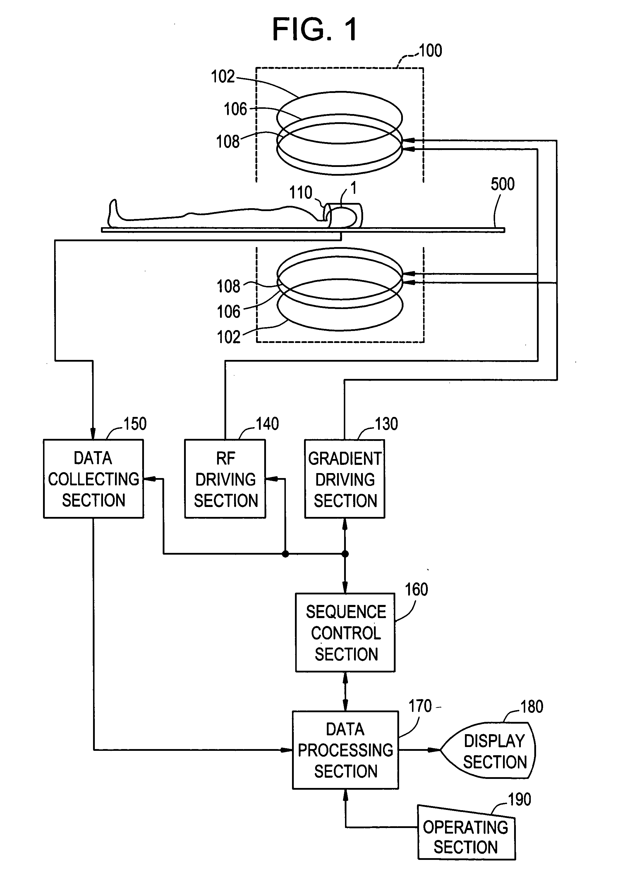
[0035] The best mode for carrying out the invention will now be described in detail with reference to the accompanying drawings. It should be noted that the present invention is not limited to the best mode for carrying out the invention. FIG. 1 shows a block diagram of an MRI apparatus. The apparatus is an example in the best mode for carrying out the present invention. The configuration of the apparatus represents an example of the MRI apparatus in the best mode for carrying out the present invention.

[0036] As shown in FIG. 1, the present apparatus has a magnet system 100. The magnet system 100 has a main magnetic field magnet section 102, a gradient coil section 106, and a transmit coil section 108. The main magnetic field magnet section 102 and the coil sections are each comprised of a pair of members facing each other across a space. These sections have a generally disk-like shape and are disposed to have a common center axis. A subject to be imaged 1 is rested on a cradle 500...


PUM


Abstract

An RF coil includes a plurality of concentric loops lying at different positions along a coil axis, whose sensitivity is improved in a central portion, and a plurality of loops are constructed as circular loops whose circles correspond to those formed by cutting a sphere common to the loops vertically with respect to the coil axis at different positions along the coil axis. Each of the plurality of loops constitutes a solenoid coil. Alternatively, a helical coil uninterruptedly running around the coil axis is formed.

Description

BACKGROUND OF THE INVENTION [0001] The present invention relates to an RF (radio frequency) coil and an MRI (magnetic resonance imaging) apparatus, and particularly to an RF coil comprising a plurality of concentric loops lying at different positions along a coil axis, and an MRI apparatus comprising such an RF coil. [0002] An RF coil is used for transmission, reception or both of RF signals in an MRI apparatus. One conventionally employed form of the RF coil is one comprising a plurality of concentric loops lying at different positions along a coil axis (for example, see Patent Document 1). [0003] [Patent Document 1] Japanese Patent Application Laid Open No. 2003-38459 (Page 5, FIG. 1). [0004] The RF coil with such a configuration in which a plurality of loops are simultaneously used has reduced combined sensitivity in the middle between adjacent loops. If an imaging center lies at such a position, the resulting image has a poor SNR (signal-to-noise ratio) in the central portion. S...

Claims


Application Information

Patent Timeline
Patent Type & Authority Applications(United States)
IPC IPC(8): A61B5/055G01R33/34
CPCG01R33/34053G01R33/3415G01R33/34069A61B5/055
Inventor SATO, KENJI
Owner GE MEDICAL SYST GLOBAL TECH CO LLC
Why Eureka
Try Eureka