Method and apparatus for driving LED's

a technology of leds and circuits, applied in pulse generators, pulse techniques, instruments, etc., can solve the problems of low power consumption and extending battery life, inefficiency of boost converters, and potentially wasteing limited battery power, and varying the forward voltage of white leds

Inactive Publication Date: 2005-04-28
SEMTECH CORP
View PDF21 Cites 46 Cited by
  • Summary
  • Abstract
  • Description
  • Claims
  • Application Information

AI Technical Summary

Benefits of technology

[0010] In one aspect, the present invention relates to a method of driving a plurality of LEDs in parallel, in at least two modes. In a first mode, the LEDs are driven with a first voltage, which may comprise a battery voltage. In a second mode, the LEDs are driven with a second, higher voltage, which may comprise a boost converter voltage. The method includes monitoring the forward voltage drop for each LED, and switching from the first mode to the second mode based on the largest of the LED forward voltage drops.
[0011] In another aspect, the present invention relates to a method of controlling the current through an LED. The method includes directing a first, predetermined current through a first digitally controlled variable resistance circuit, and directing a second current through a series circuit comprising the LED and a second digitally controlled variable resistance circuit having substantially a known ratio to the first variable resistance circuit. A digital count

Problems solved by technology

While this provides sufficient drive to power the LEDs, the inefficiency of the boost converter potentially wastes limited battery power.
As one example, many newer cellular telephones include an “internet mode,” displaying text data (such as on an LCD screen) that is transmitted at a v

Method used


Image

  • Method and apparatus for driving LED's
  • Method and apparatus for driving LED's
  • Method and apparatus for driving LED's

Examples


Embodiment Construction

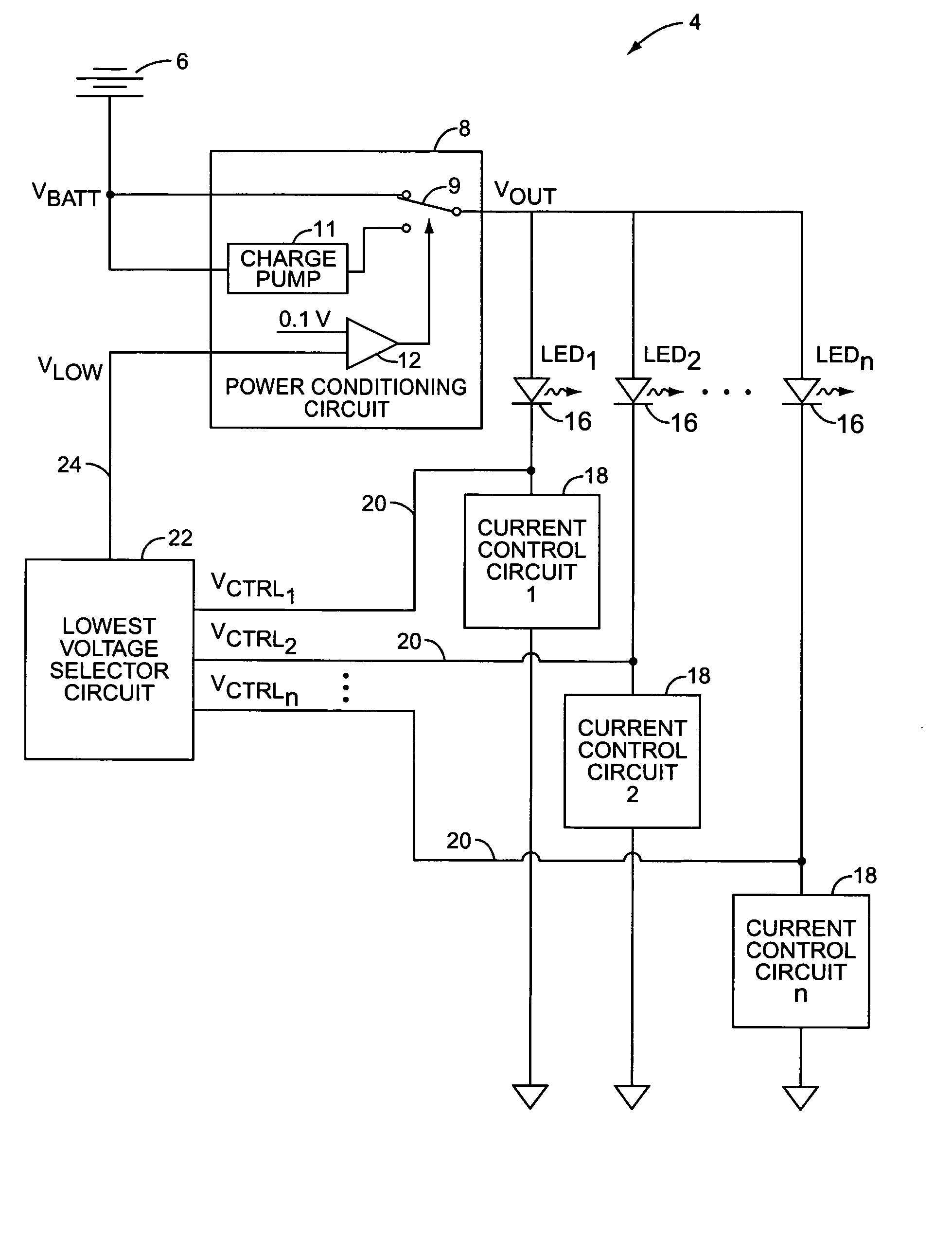
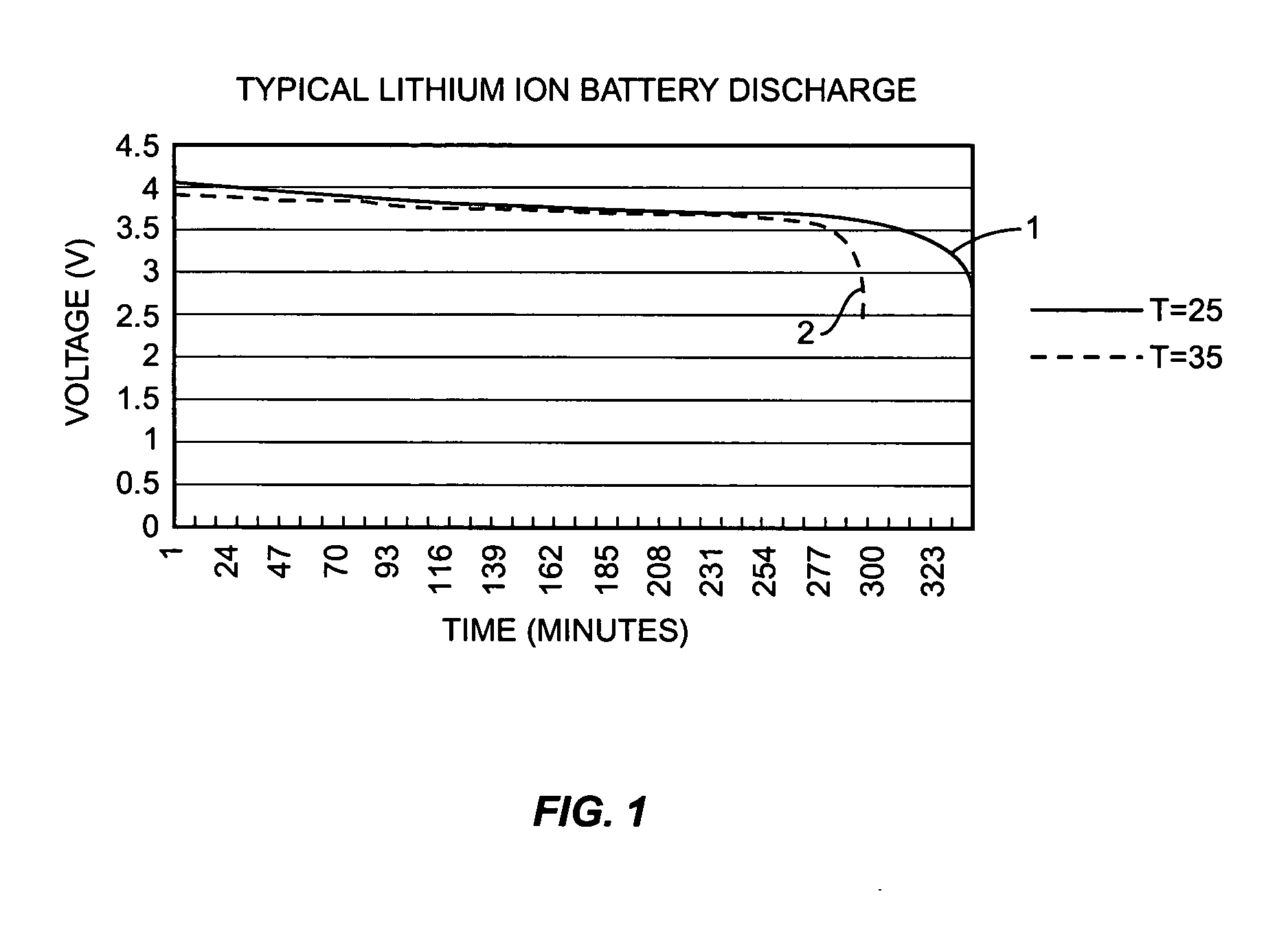
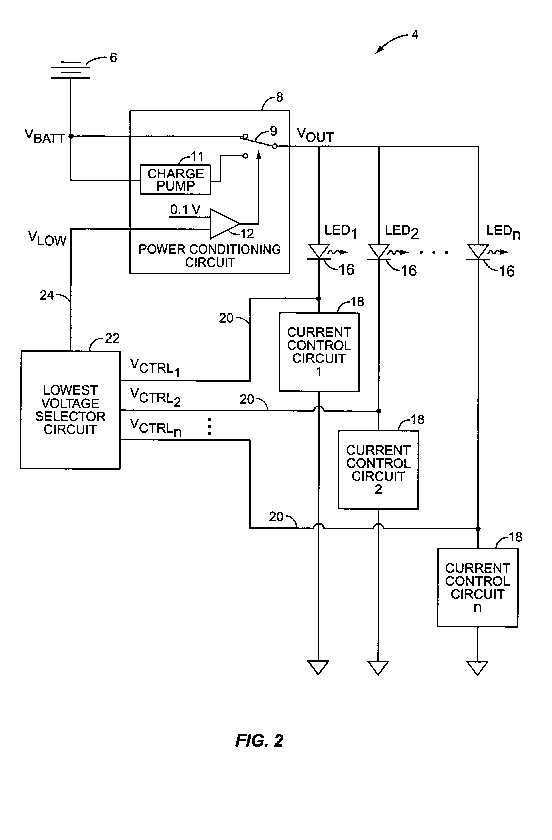
[0019]FIG. 2 depicts, in functional block diagram form, a power supply and current control circuit, indicated generally by the numeral 10, for driving a plurality of LEDs 16 from a battery 6, which is preferably a lithium ion battery having a discharge profile similar to that depicted in FIG. 1. The battery 6 provides an output voltage VBATT to a power conditioning circuit 8, which in turn provides an output voltage VOUT. VOUT powers a plurality of LEDs 16, connected in parallel. Connected in series with each LED 16 is a current control circuit 18 that controls the current through the corresponding LED 16 to a predetermined level. The voltage drop across each current control circuit 18, measured at tap 20, is supplied to a lowest voltage selector circuit 22. The selector circuit 22 isolates and forwards the lowest of the tapped voltages, VLOW 24, to the power conditioning circuit 8.

[0020] Power conditioning circuit 8 operates in two modes. In a first, or battery mode, VOUT is taken...


PUM


Abstract

A plurality of LEDs is driven in parallel, in at least two modes. In a first mode, the LEDs are driven with a first voltage. In subsequent modes, the LEDs are driven with successively higher voltages. The forward voltage drop for each LED is monitored, and the driver switches from the first mode to successive modes based on the largest of the LED forward voltage drops. The current through each LED is controlled by directing a reference current through a first digitally controlled variable resistance circuit, and directing the LED current through a second digitally controlled variable resistance circuit having substantially a known ratio to the first variable resistance circuit and connected in series with the LED. A digital count is altered based on a comparison of the first and second currents, and the first and second variable resistance circuits are simultaneously altered based on the digital count.

Description

BACKGROUND OF THE INVENTION [0001] The present invention relates generally to battery-powered circuits for LEDs, and particularly to a system and method of driving LEDs. [0002] Rechargeable batteries are utilized as a power source in a wide variety of electronic devices. In particular, rechargeable batteries are utilized in portable consumer electronic devices such as cellular telephones, portable computers, Global Positioning System (GPS) receivers, and the like. Many of these devices employ a rechargeable lithium ion battery, with a typical output voltage in the range of 3V to 4.2V. [0003] A fairly recent development in solid state electronics is the development of the white-light LED. White LEDs offer significant advantages over alternative white-light sources, such as small incandescent bulbs or fluorescent lights. Among these are greater efficiency (resulting in lower heat generation and lower power consumption for a given level of illumination), increased operating life, and s...

Claims


Application Information

Patent Timeline
IPC IPC(8): G05F1/00G09G3/10G09G3/32G09G3/34H03B1/00H03K5/22
CPCG09G3/342G09G2320/0233H05B33/0887H05B33/0815H05B33/0827G09G2330/021H05B45/46H05B45/38H05B47/17
Inventor RADER, WILLIAM E.FORAN, RYAN P.
Owner SEMTECH CORP
Why Eureka
Try Eureka