Power amplifier module

Inactive Publication Date: 2005-04-28
RENESAS ELECTRONICS CORP
View PDF9 Cites 5 Cited by
  • Summary
  • Abstract
  • Description
  • Claims
  • Application Information

AI Technical Summary

Benefits of technology

[0007] An object of the present invention is to solve the problems of the above-described prior art and also the problems of the above-explained prior-investigated technical examples, and is to provide a low-cost power amplifier module which owns a high efficiency and a high linear characteristic, and further, can be easily manufactured in an integrated circuit form.
[0009] In the present invention, an input signal is supplied via individual capacitors to the reference amplifier and the respective stage amplifiers. At this time, although the current responding to the input power level flows through the input terminal of the reference amplifier, no current flow through the input terminals of the respective stage amplifiers. Therefore, if a DC component of the input current of the reference amplifier is detected and amplified, and the detected / amplified DC component current is supplied to the input terminals of the respective stage amplifiers, then the respective stage amplifiers commence high frequency operations. When the input power level is increased, the input current of the reference amplifier is increased, so that the input currents supplied to the respective stage amplifiers are also increased. Conversely, when the input power level is lowered, the input current of the reference amplifier is decreased, so that the input currents supplied to the respective stage amplifiers are also decreased. In other words, since the operating point corresponding to the input power can be set, even when the small input power is supplied, a relatively high efficiency can be obtained.

Problems solved by technology

In particular, as to power amplifier modules which constitute one of major electronic components of terminal units, there is such a serious problem that these contradicting performance requirements are realized at the same time.
However, since this DC voltage generating circuit 103 must be separately provided with reference to the amplifiers 101 and 102, there is such a problem that the stable characteristic of this DC voltage generating circuit 103 can be continuously and hardly guaranteed without any adjustment with respect to variations of environment conditions such as manufacturing deviation and ambient temperatures, and also power supply voltages.
However, there are such problems that the use of such a DC-to-DC converter may constitute a factor of impeding the integrating manufacture of electronic components, and furthermore, the module is made bulky as well as the manufacturing cost is increased.
In this circuit system, since the output of the reference transistor, namely, the voltage at the bias point corresponding to the base input of the main transistor is not substantially changed in connection with the change in the input amplitudes, there is a problem that the output of the reference transistor can hardly give effectively influences to up / down of the operating point of the main transistor.

Method used


Image

  • Power amplifier module
  • Power amplifier module
  • Power amplifier module

Examples


Embodiment Construction

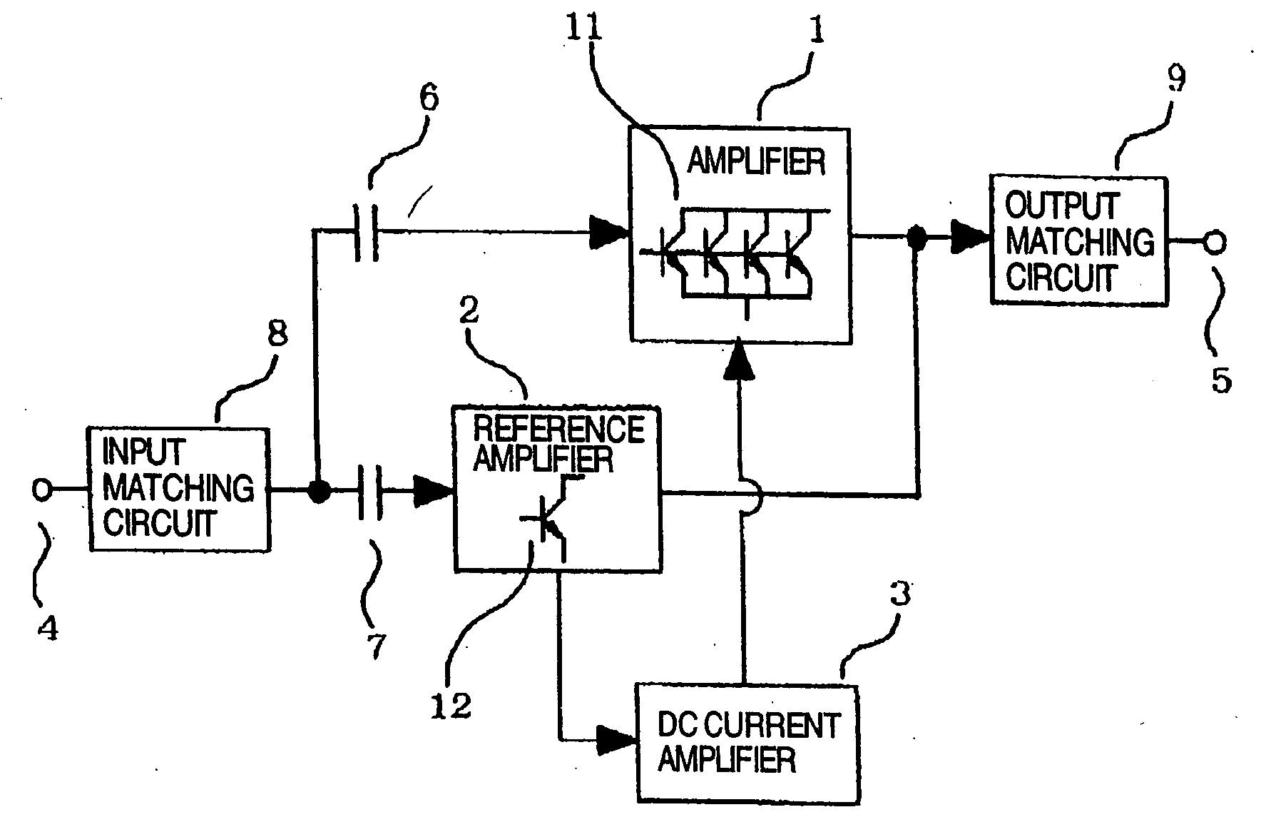
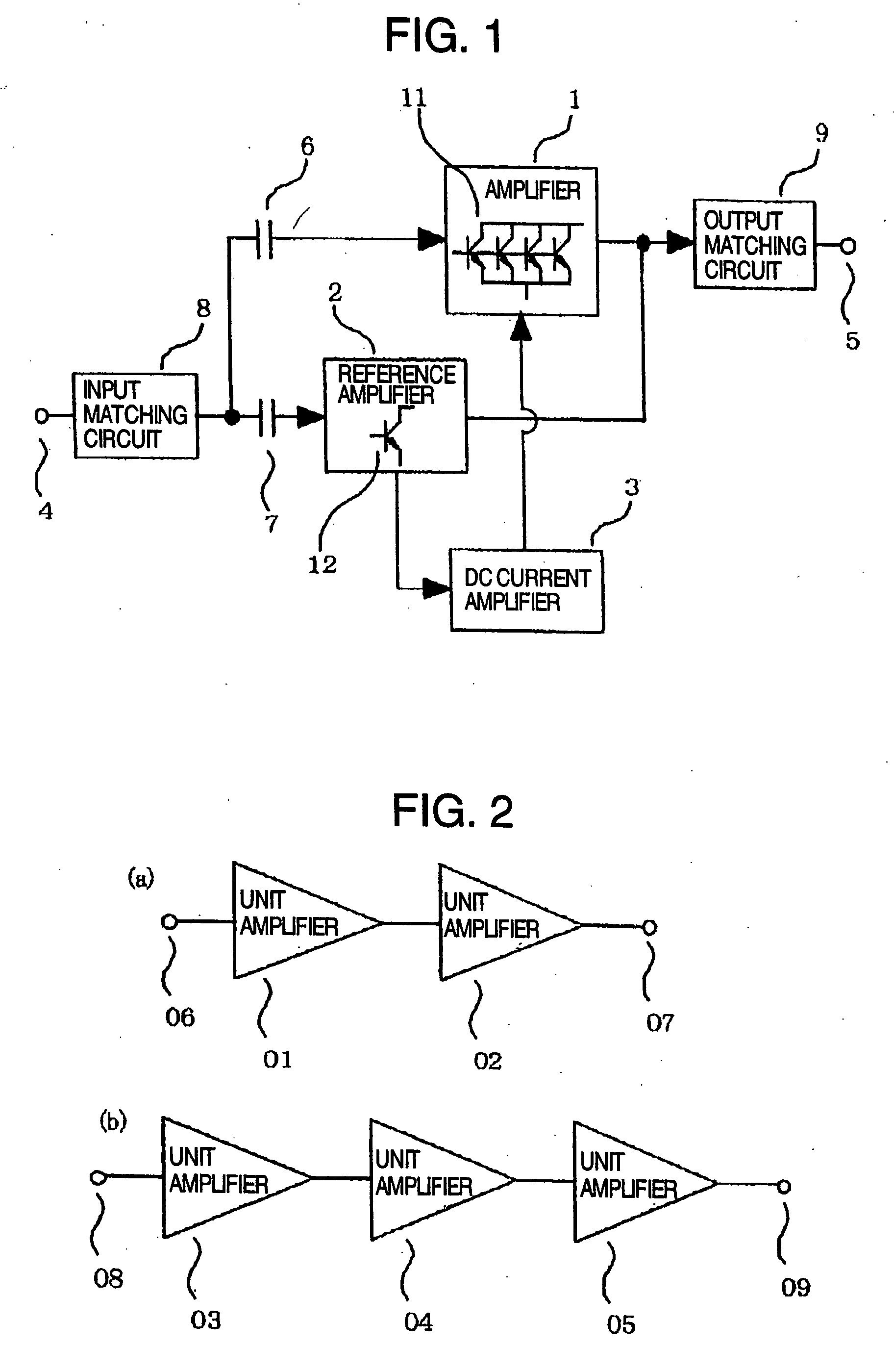
[0021] In general, a power amplifier module is arranged by employing either two stages or three stages of unit amplifiers. FIG. 1 represents an embodiment of unit amplifiers which constitute a power amplifier module according to the present invention. The unit amplifier of this embodiment is constituted by an amplifier 1 for power-amplifying an input signal, a reference amplifier 3, a DC current amplifier 3, input / output matching circuits 8 and 9, and also, coupling capacitors 6 and 7. The reference amplifier 2 produces a DC component of an input current in correspondence with a level of input power. The DC current amplifier 3 amplifies this DC current component, and then supplies this current-amplified DC component to the amplifier 1. In this case, in such a case that a dimension ratio of a transistor 11 to another transistor 12 is equal to n:1, which constitute both the amplifier 1 and the reference amplifier 2, a current amplification factor of the DC current amplifier 3 is set t...


PUM


Abstract

A CDMA system is provided which includes a power amplifier module have a DC current amplifier. The DC and current amplifier detects a DC component of an input signal and amplifies this detected DC component. The power amplifier module also includes an amplifier which receives the current amplified by the DC current amplifier as an input current. The input signal supplied to the DC current amplifier changes in response to an input power level.

Description

TECHNICAL FIELD [0001] The present invention relates to a power amplifier, module designed for a portable terminal unit used in a mobile communication system. More specifically, the present invention is related to a power amplifier module designed for a cellular telephone system requiring a high efficiency and high linearity. BACKGROUND ART [0002] As conventional techniques related to power amplifier modules, there are JP-A-7-154169 and U.S. Pat. No. 5,629,648. [0003] Very recently, while mobile communication markets typically known as cellular telephone systems are considerably expanded, new communication systems such as the broadband CDMA system and the EDGE system have been conducted. In such systems, high efficiencies and high linearity of portable terminal units are required. In particular, as to power amplifier modules which constitute one of major electronic components of terminal units, there is such a serious problem that these contradicting performance requirements are rea...

Claims


Application Information

Patent Timeline
IPC IPC(8): H03F1/02H03F3/68H03F1/30H03F1/32H03F3/19H03F3/193H03F3/213
CPCH03F1/0222H03F1/0261H03F1/0266H03F1/301H03F1/302H03F2200/453H03F1/56H03F3/19H03F3/1935H03F2200/318H03F1/306
Inventor MATSUMOTO, HIDETOSHITANOUE, TOMONORITANAKA, SATOSHIYAMASHITA, KIICHI
Owner RENESAS ELECTRONICS CORP
Why Eureka
Try Eureka