Micro-fluid ejection devices and method therefor

a technology of ejection device and microfluid, which is applied in printing and other directions, can solve the problems of limited choices available for nozzle plate material thickness, reduced printhead performance, and suboptimal performance, and achieves the effect of increasing the cross sectional area of the ink feed channel, and increasing the freedom of movemen

Active Publication Date: 2005-04-28
FUNAI ELECTRIC CO LTD
View PDF15 Cites 10 Cited by
  • Summary
  • Abstract
  • Description
  • Claims
  • Application Information

AI Technical Summary

Benefits of technology

[0008] An advantage of the invention is that it enables independent variation of the nozzle bore length and the flow feature height. Independent variation of the nozzle bore length and flow feature height is achieved by combining flow features formed in thick film layer with flow features and nozzle holes formed in a nozzle plate material. As a result, the invention enables more freedom to design flow features and nozzles for printheads that produce the best quality images without resorting to the use of non-conventional nozzle plate material thicknesses.
[0009] Another advantage of the invention is that the cross sectional area of the ink feed channels to the ink chambers can be increased without affecting the nozzle bore length. An increase in the cross sectional area of the ink feed channel can be used to decrease the refill time of the ink chambers and therefore increase the operating or firing frequency of the printhead. An increased cross sectional area may be especially helpful for ink chambers positioned relatively far from the ink feed slot. In that regard, adjacent ink feed channels and ink chambers may be provided with different cross-sectional dimensions in the same printhead. This advantage is not easily provided by conventional printhead fabrication methods.

Problems solved by technology

A disadvantage of forming the flow features and nozzle holes in the nozzle plate material is that the flow feature height and nozzle bore length are constrained by the nozzle plate material thickness.
Unfortunately, there are limited choices available for the nozzle plate material thickness.
The restriction on nozzle plate material thickness often leads to compromises in flow feature design and / or nozzle dimensions which may lead to reduced printhead performance and suboptimal performance.

Method used


Image

  • Micro-fluid ejection devices and method therefor
  • Micro-fluid ejection devices and method therefor
  • Micro-fluid ejection devices and method therefor

Examples


Embodiment Construction

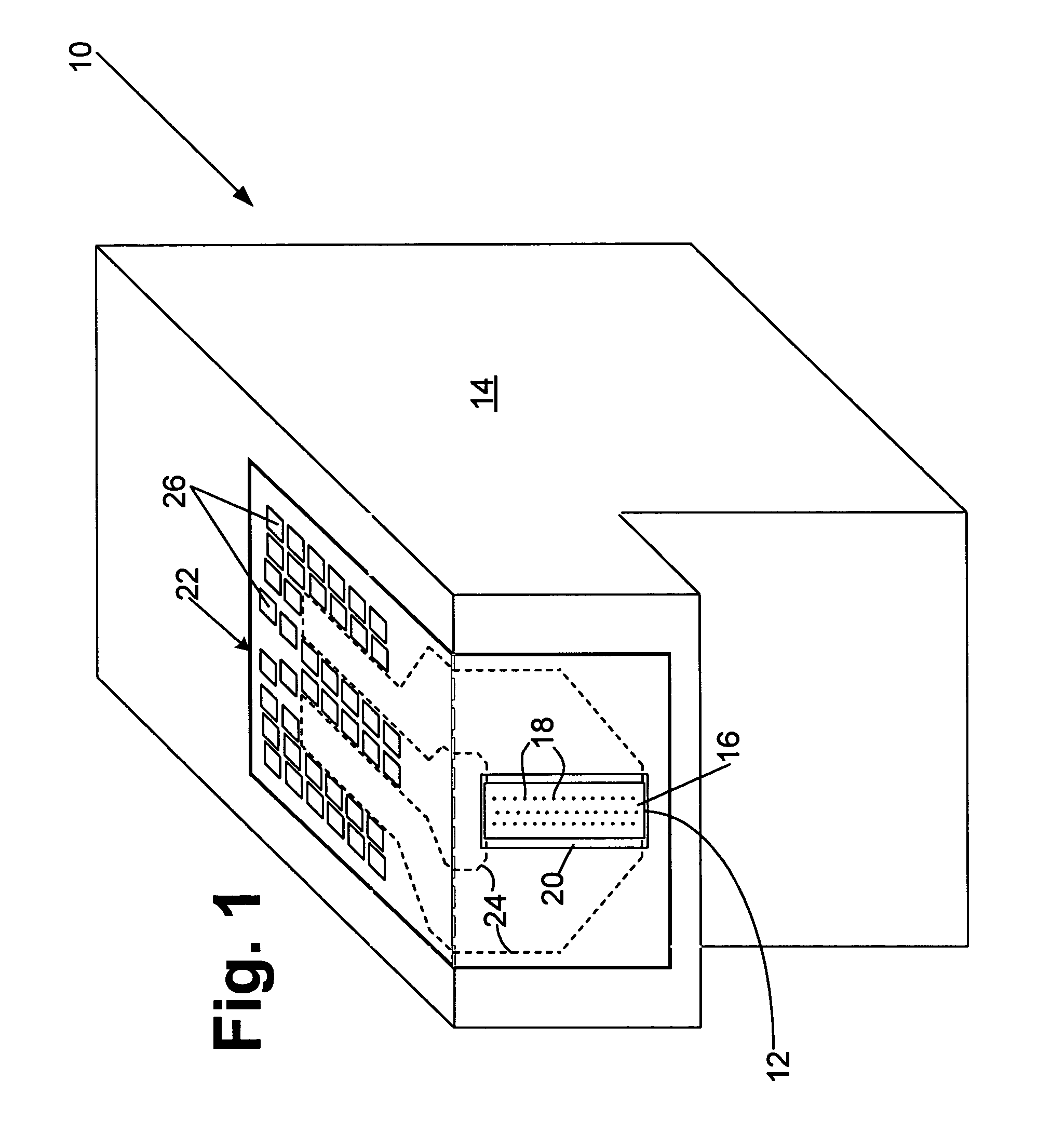
[0017] With reference to FIG. 1, a fluid supply cartridge 10 for use with a device such as an ink jet printer includes a printhead 12 fixedly attached to a fluid supply container 14 as shown in FIG. 1 or removably attached to a fluid supply container either adjacent to the printhead 12 or remote from the printhead 12. In order to simplify the description, reference will be made to inks and ink jet printheads. However, the invention is adaptable to other micro-fluid ejecting devices other than for use in ink jet printers and thus is not intended to be limited to ink jet printers.

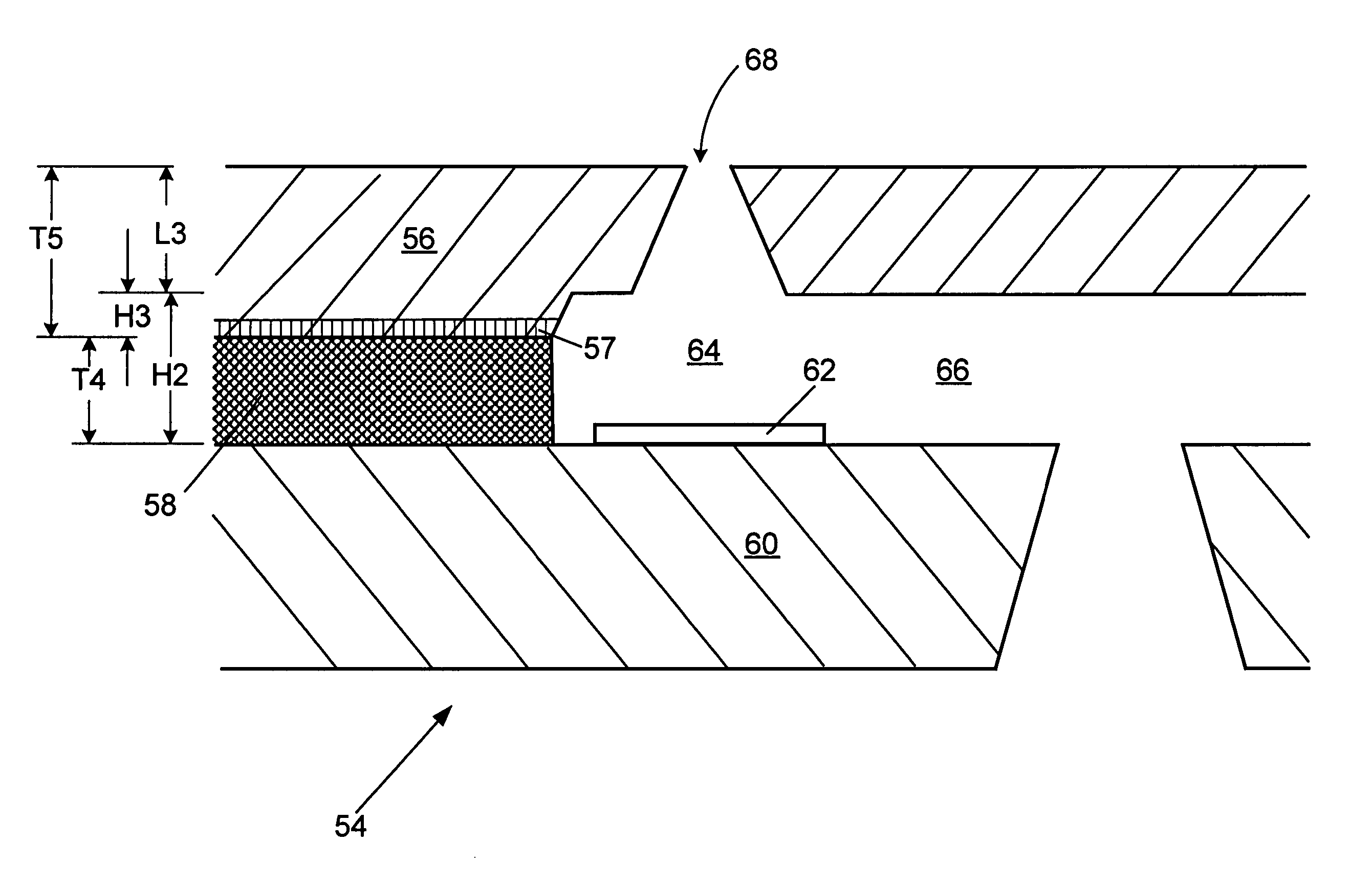
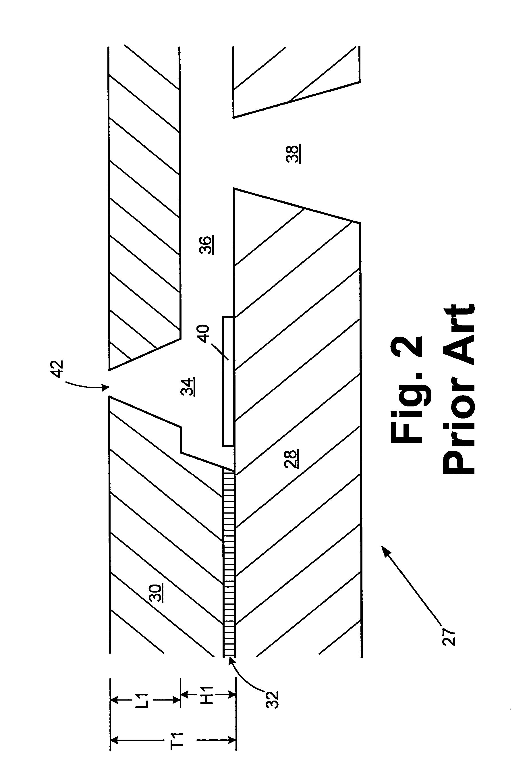
[0018] The printhead 12 preferably contains a nozzle plate 16 containing a plurality of nozzle holes 18 each of which are in fluid flow communication with a fluid in the supply container 14. The nozzle plate 16 is preferably made of an ink resistant, durable material such as polyimide and is attached to a semiconductor substrate 20 that contains ink ejection devices as described in more detail below. The sem...


PUM


Abstract

An improved ink jet printhead for an ink jet printer and method therefor. The printhead includes a semiconductor substrate containing ink ejection devices. A thick film layer is attached to the substrate. A nozzle plate is attached to the thick film layer. The nozzle plate contains a plurality of ink ejection nozzles corresponding to the ink ejection devices. The printhead contains flow features having a height dimension and a width dimension formed therein for flow of ink to the plurality of ink ejection devices for ejection through the nozzles. At least a portion of the flow feature dimensions for at least one of the nozzles is formed in both the thick film layer and laser ablated in the nozzle plate, wherein the thick film layer contains at least 12% of the flow feature dimensions.

Description

FIELD OF THE INVENTION [0001] The invention relates to micro-fluid ejection devices such as ink jet printheads and methods for making micro-fluid ejection devices having improved ink flow characteristics. BACKGROUND [0002] A conventional micro-fluid ejection device such as an ink jet printhead generally has flow features either formed in a thick film layer deposited on a semiconductor substrate containing ink ejection devices or flow features ablated along with nozzles holes in a polymeric nozzle plate material. The term “flow features” is used to refer to ink chambers and ink supply channels that provide a fluid such as ink to ejection devices on the semiconductor substrate for ejection through nozzle holes. When both the nozzle holes and flow features are ablated in the nozzle plate material, a thick film material is not present. A disadvantage of forming the flow features and nozzle holes in the nozzle plate material is that the flow feature height and nozzle bore length are cons...

Claims


Application Information

Patent Timeline
Patent Type & Authority Applications(United States)
IPC IPC(8): B41J2/14B41J2/16
CPCB41J2/1404B41J2/1634B41J2/1603
Inventor GOIN, RICHARD LOUISMAHER, COLIN GEOFFREYPOWERS, JAMES HAROLD
Owner FUNAI ELECTRIC CO LTD
Why Eureka
Try Eureka