[0084] Consequently, when a
ray emitted from the LED 32 and condensed by the condensing body 33 is irradiated on the surface of the document, as the condensing body 33 is closer to the reading
light reflection area B, even if the document on the contact glass 12 gets lifted, a quantity of light rays irradiated on the surface of the document above the reading
optical axis A can be secured more, lighting performance of the lighting apparatus 18 is maintained better, and reading performance of the image reading apparatus 13 is maintained better.
[0096] Rays irradiated on the surface of the document on the contact glass 12 are divided into rays, which pass through the direct emitting portion 52 of the condensing body 33 and are directly irradiated, and rays, which are emitted from the indirect emitting portion 53 of the condensing body 33 and irradiated via the reflection mechanism 42. These two kinds of rays are irradiated toward the surface of the document above the reading
optical axis A from both sides in the sub-scanning direction at the time of image reading across the reading
optical axis A. Therefore, the position of a
peak value of a quantity of light of rays irradiated on the surface of the document can be brought closer to the reading optical axis A.
[0046]FIG. 20 is a front view of a lighting device according to a twelfth embodiment of the present invention FIG. 21 is a front view of a lighting device and a first mirror that are mounted on a first traveling body;
[0096] Rays irradiated on the surface of the document on the contact glass 12 are divided into rays, which pass through the direct emitting portion 52 of the condensing body 33 and are directly irradiated, and rays, which are emitted from the indirect emitting portion 53 of the condensing body 33 and irradiated via the reflection mechanism 42. These two kinds of rays are irradiated toward the surface of the document above the reading optical axis A from both sides in the sub-scanning direction at the time of image reading across the reading optical axis A. Therefore, the position of a
peak value of a quantity of light of rays irradiated on the surface of the document can be brought closer to the reading optical axis A.
[0049]FIG. 24 is a disassembled perspective view of a lighting device according to a fourteenth embodiment of the present invention;
[0104] The reflection plate 73 has a function of condensing rays, which have passed through the
light guide member 38, toward the surface of the document on the contact glass 12 above the reading optical axis A and a function of reflecting a part of the rays, which have passed through the
light guide member 38, to the second reflection plate 44. The reflection plate 73 and the second reflection plate 44 constitute the reflection mechanism 42 that reflects a part of the rays, which have emitted from the condensing body 72, from the opposite side across the reading optical axis A.
[0071] In such a structure, angles of all rays, which have been emitted from the LED 32 and have passed through the condensing body 33, are maintained to be smaller than the critical angle “θ” of the contact glass 12. Thus, the rays are transmitted through the contact glass 12 without being reflected by the contact glass 12 and are irradiated on the surface of the document. Consequently, all the rays emitted from the LEDs 32 can be utilized effectively to light the surface of the document. Therefore, even in the case in which the LEDs 32, which are point light sources with a small quantity of light, are used as light sources for the lighting device 18, a quantity of light necessary for image reading can be secured.
[0084] Consequently, when a
ray emitted from the LED 32 and condensed by the condensing body 33 is irradiated on the surface of the document, as the condensing body 33 is closer to the reading
light reflection area B, even if the document on the contact glass 12 gets lifted, a quantity of light rays irradiated on the surface of the document above the reading optical axis A can be secured more, lighting performance of the lighting apparatus 18 is maintained better, and reading performance of the image reading apparatus 13 is maintained better.
[0053]FIG. 28 is a side view explaining a state in which rays emitted from LEDs and transmitted through a condensing body are diffused at random in a light diffusing portion;
[0071] In such a structure, angles of all rays, which have been emitted from the LED 32 and have passed through the condensing body 33, are maintained to be smaller than the critical angle “θ” of the contact glass 12. Thus, the rays are transmitted through the contact glass 12 without being reflected by the contact glass 12 and are irradiated on the surface of the document. Consequently, all the rays emitted from the LEDs 32 can be utilized effectively to light the surface of the document. Therefore, even in the case in which the LEDs 32, which are point light sources with a small quantity of light, are used as light sources for the lighting device 18, a quantity of light necessary for image reading can be secured.
[0079] As another one of the contrivances for providing the condensing body 33 close to the reading light reflection area B, the LEDs 32 are formed in an elongated shape toward a direction along the main scanning direction at the time of image reading. In other words, the LEDs 32 are designed to have a shape in which a width dimension L in the sub-scanning direction when reading the document is reduced. This makes it possible to provide a central position of the LEDs 32 attached to the substrate 36a closer to the width direction of the substrate 36a, and the condensing body 33 can be provided closer to the reading light reflection area B.
[0075] Therefore, when the surface of the document is lighted using this condensing body 33a, rays condensed by the condensing body 33a are transmitted through and irradiated on the surface of the document without being reflected on the contact glass 12. Thus, all rays emitted from the LEDs 32 can be utilized effectively to light the surface of the document.
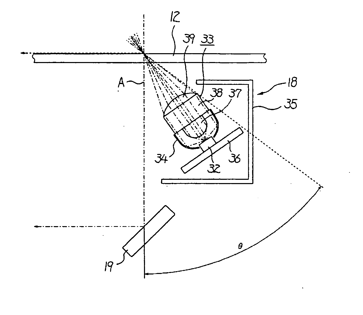
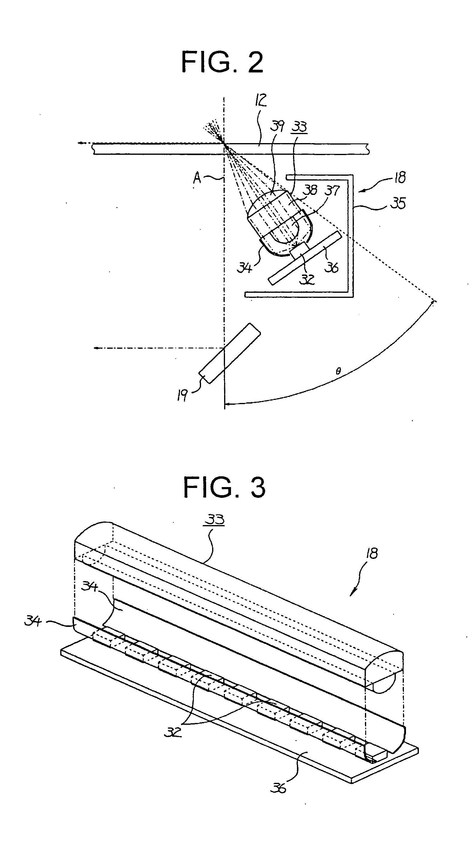
[0066] The condensing body 33 includes a lens 37, a
light guide member 38, and a
condensing lens 39, which are integrally molded, and is formed in an elongated shape having substantially the same length as the substrate 36. The condensing body 33 is positioned in such a manner that its length is aligned with the main scanning direction of reading the document.
[0066] The condensing body 33 includes a lens 37, a light guide member 38, and a
condensing lens 39, which are integrally molded, and is formed in an elongated shape having substantially the same length as the substrate 36. The condensing body 33 is positioned in such a manner that its length is aligned with the main scanning direction of reading the document.
[0066] The condensing body 33 includes a lens 37, a light guide member 38, and a condensing lens 39, which are integrally molded, and is formed in an elongated shape having substantially the same length as the substrate 36. The condensing body 33 is positioned in such a manner that its length is aligned with the main scanning direction of reading the document.
[0095] The indirect emitting portion 53 is formed by
cutting a part of the condensing lens 39 and a part of the light guide member 38 and is also
cut in a direction in which rays emitted from the indirect emitting portion 53 travel toward the first reflection plate 43.
[0095] The indirect emitting portion 53 is formed by
cutting a part of the condensing lens 39 and a part of the light guide member 38 and is also
cut in a direction in which rays emitted from the indirect emitting portion 53 travel toward the first reflection plate 43.

