Actuator

a technology of actuators and actuators, applied in the field of actuators, can solve the problems of increasing manufacturing costs, difficult to miniaturize the size of the apparatus in which the polygon mirror is used, and difficult to rotate the polygon mirror at a much higher speed, etc., and achieves large displacement, large rotation angle, and large deflection angle.

Inactive Publication Date: 2005-04-28
SEIKO EPSON CORP
View PDF1 Cites 26 Cited by
  • Summary
  • Abstract
  • Description
  • Claims
  • Application Information

AI Technical Summary

Benefits of technology

[0008] It is therefore an object of the present invention to provide an actuator capable of operating at high speed and at low voltage and achieving a large displacement (that is, large rotation angle or large deflection angle).

Problems solved by technology

However, there is a problem in that it is difficult to rotate the polygon mirror at much higher speed than the speed available at the present.
Further, although a larger motor is required in order to rotate the polygon mirror at higher speed, use of such a larger motor arises a problem in that it is difficult to miniaturize the size of an apparatus in which the polygon mirror is used.
Furthermore, use of such a polygon mirror arises another problem in that the structure of the apparatus becomes necessarily complicated, thus leading to increased manufacturing cost.
Therefore, if the electrode interval becomes too small, a movable range (rotation angle) of the movable electrode portion is necessarily limited.
Namely, such a single-degree-of-freedom torsional vibrator described above involves a problem in that it is difficult to achieve both of low-voltage driving and large displacement.

Method used


Image

  • Actuator
  • Actuator
  • Actuator

Examples


Embodiment Construction

[0032] Hereinafter, preferred embodiments of an actuator according to the present invention will be described with reference to the appended drawings.

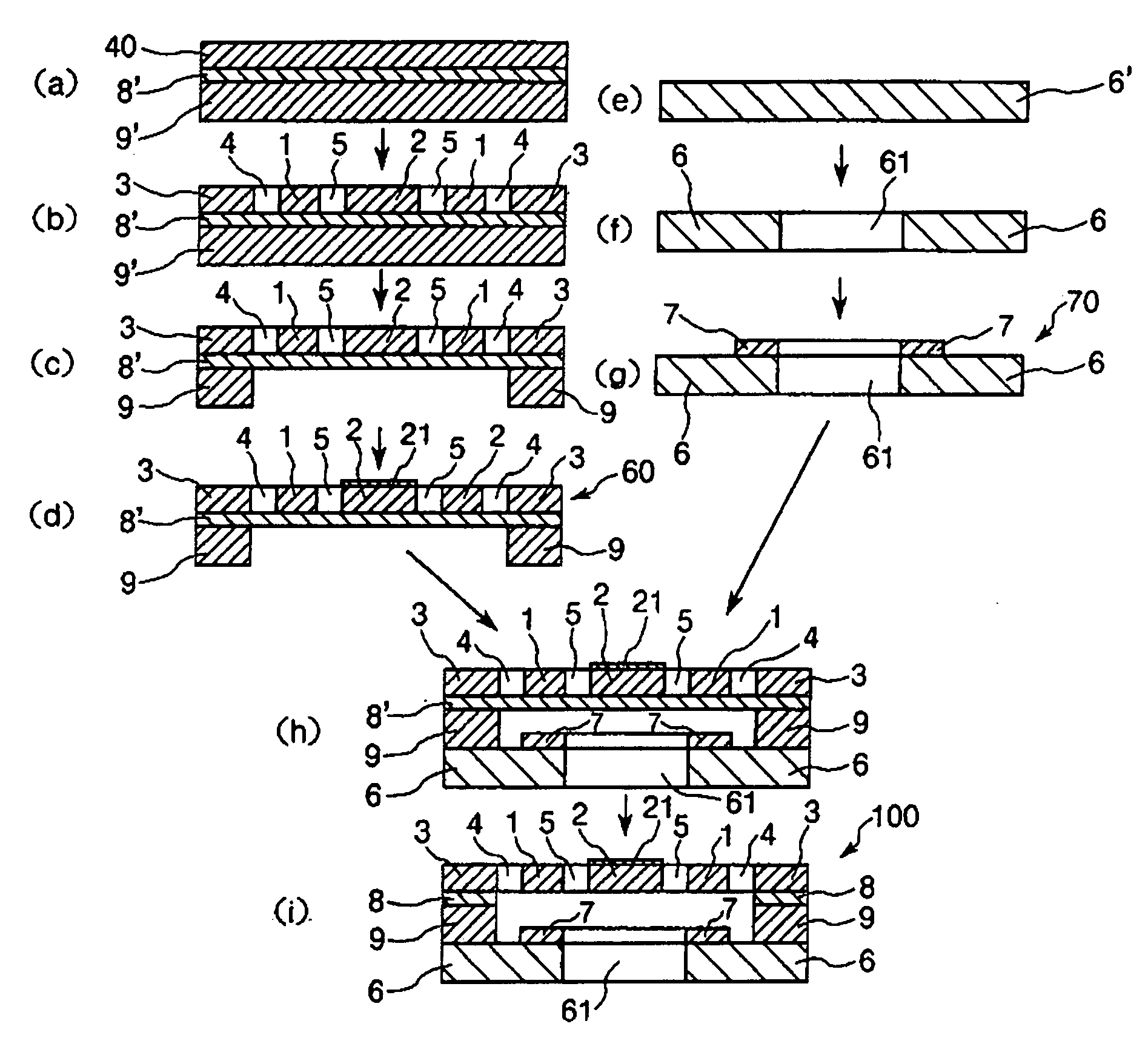
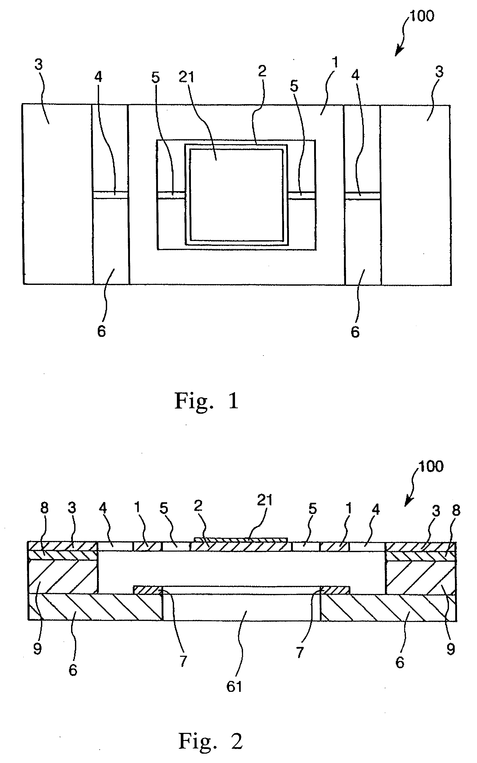
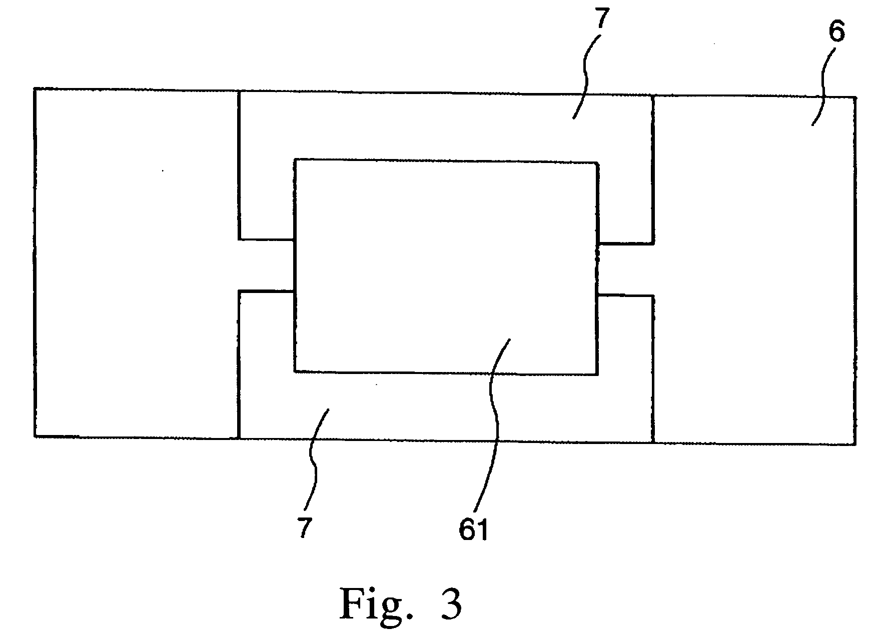
[0033] First, a first embodiment of the actuator according to the present invention will be described. FIG. 1 is a plan view which shows the first embodiment of the actuator according to the present invention, FIG. 2 is a cross-sectional view which shows the first embodiment of the actuator according to the present invention, FIG. 3 is a plan view which shows a counter substrate and electrodes of the first embodiment, and FIG. 4 is a graph which shows the frequency of an alternating voltage applied and the resonance curves of a first mass portion and a second mass portion.

[0034] An actuator 100 shown in FIG. 1 includes a first mass portion (that is, a driving portion) 1, a second mass portion (that is, a movable portion) 2, and a pair of supporting portions 3. Each of the first mass portion 1, the second mass portion 2, and the suppo...


PUM


Abstract

An actuator of the type employing a two-degree-of-freedom vibration system includes a first mass portion, a second mass portion, a pair of supporting portions, as least a pair of first elastic connecting portions which connects the first mass portion to the supporting portion so that the first mass portion can rotate with respect to the supporting portion, and at least a pair of second elastic connecting portions which connects the second mass portion to the first mass portion so that the second mass portion can rotate with respect to the first mass portion. The first mass portion is driven by the application of an alternating voltage, causing the second mass portion to rotate, and the frequency of the alternating voltage is set so as to be substantially the same as a lower resonance frequency of resonance frequencies of the two-degree-of-freedom vibration system at which the first mass portion and the second mass portion resonate. This makes it possible to provide the actuator capable of operating at high speed and at low voltage and achieving a large rotation angle.

Description

BACKGROUND OF THE INVENTION [0001] 1. Field of the Invention [0002] The present invention relates to an actuator, and in particular relates to an actuator of the type employing a two-degree-of-freedom vibration system. [0003] 2. Description of the Prior Art [0004] There is known a polygon mirror (rotary polyhedron), which is used in an optical scanner provided in laser printers, for example. In such a printer, in order to achieve higher-resolution and higher-quality printed output as well as higher-speed printing, it is necessary to rotate the polygon mirror at higher speed. Currently, an air bearing is used to rotate the polygon mirror at high speed with stability. However, there is a problem in that it is difficult to rotate the polygon mirror at much higher speed than the speed available at the present. Further, although a larger motor is required in order to rotate the polygon mirror at higher speed, use of such a larger motor arises a problem in that it is difficult to miniatur...

Claims


Application Information

Patent Timeline
Patent Type & Authority Applications(United States)
IPC IPC(8): B81B3/00G02B26/08H02N1/00G02B26/10
CPCG02B26/0841H02N1/006G02B26/085
Inventor YODA, MITSUHIRO
Owner SEIKO EPSON CORP
Why Eureka
Try Eureka