Microscope drape lens protective cover assembly

a technology of protective cover and microscope, which is applied in the field of microscope drape lens protective cover assembly, can solve the problems of affecting the surgeon's view of the surgical site, affecting the operation, and affecting the operation, so as to facilitate the operation, facilitate the attachment, and facilitate the adjustment of the holder

Inactive Publication Date: 2005-04-28
TIDI CFI PROD
View PDF34 Cites 37 Cited by
  • Summary
  • Abstract
  • Description
  • Claims
  • Application Information

AI Technical Summary

Benefits of technology

[0008] Another frequently encountered problem when using surgical microscopes is that the optical path from the surgical site to the eyepieces may be distorted, obscured, or blurred by the reflection or refraction of light either from the illuminating source or from other lighting in the area where the surgery is being conducted. Sometimes the lens cover or shield when in its best position for optical acuity is subjected to glare which cannot be removed if the lens is to remain in its optimum position. Apparatus constructed in accordance with the invention provides an additional or secondary holder for a shield or cover which can be applied to the objective lens barrel in such manner as to enable the shield to be both rocked and rotated to any selected one of a number of adjusted positions in which the visual acuity is optimum. The construction of the apparatus according to the invention is such as to facilitate not only the attachment of the additional shield holder to the lens barrel but also enable extremely rapid and facile adjustment of the holder and the shield carried thereby, while ensuring snug retention of the holder in its selected position of adjustment.

Problems solved by technology

Contamination of the lens interferes with the surgeon's view of the surgical site.
The cleaning or replacement of a contaminated lens shield or cover frequently is hampered by the necessity of the person charged with cleaning or replacement to be gloved.
Another frequently encountered problem when using surgical microscopes is that the optical path from the surgical site to the eyepieces may be distorted, obscured, or blurred by the reflection or refraction of light either from the illuminating source or from other lighting in the area where the surgery is being conducted.

Method used


Image

  • Microscope drape lens protective cover assembly
  • Microscope drape lens protective cover assembly
  • Microscope drape lens protective cover assembly

Examples


Embodiment Construction

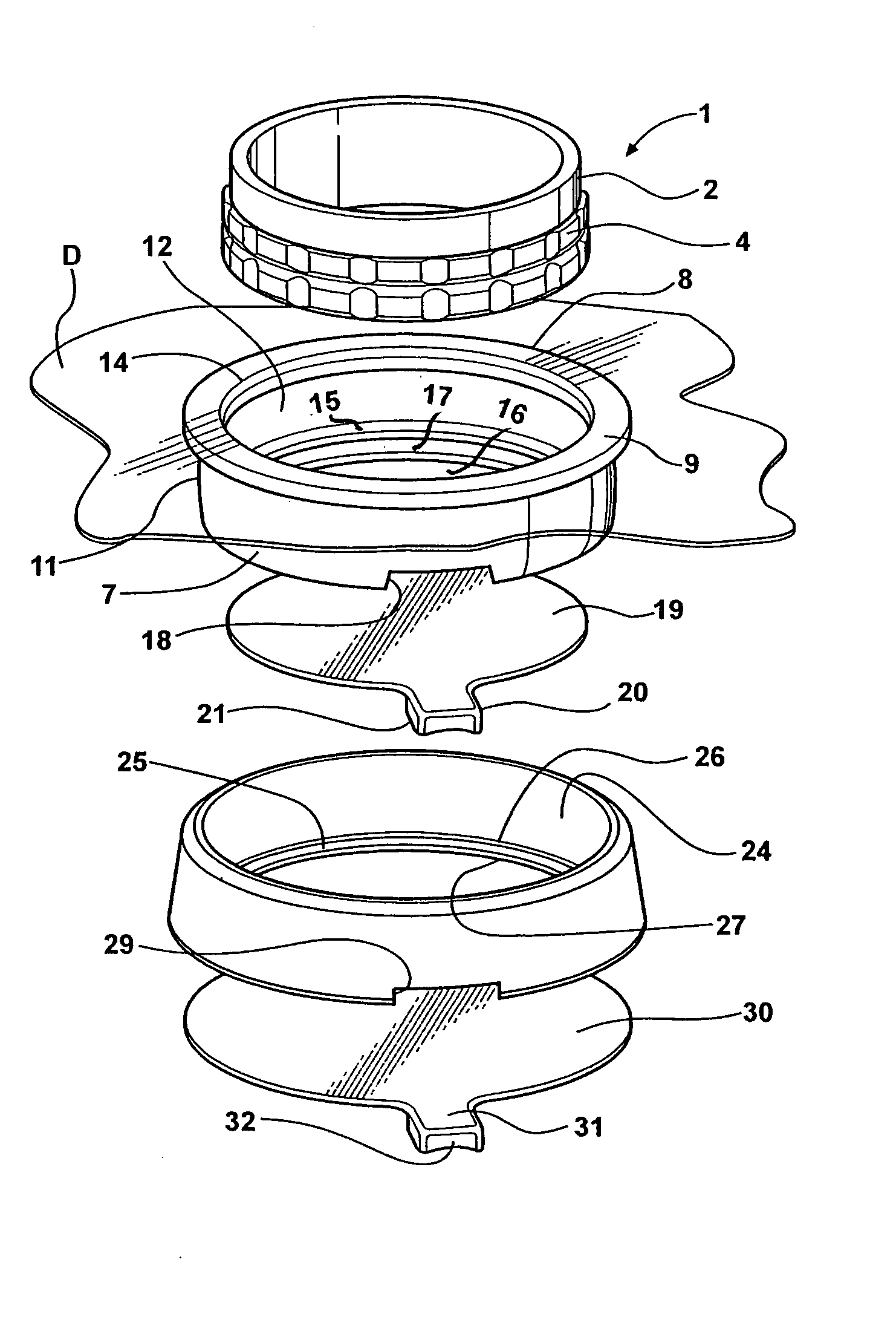
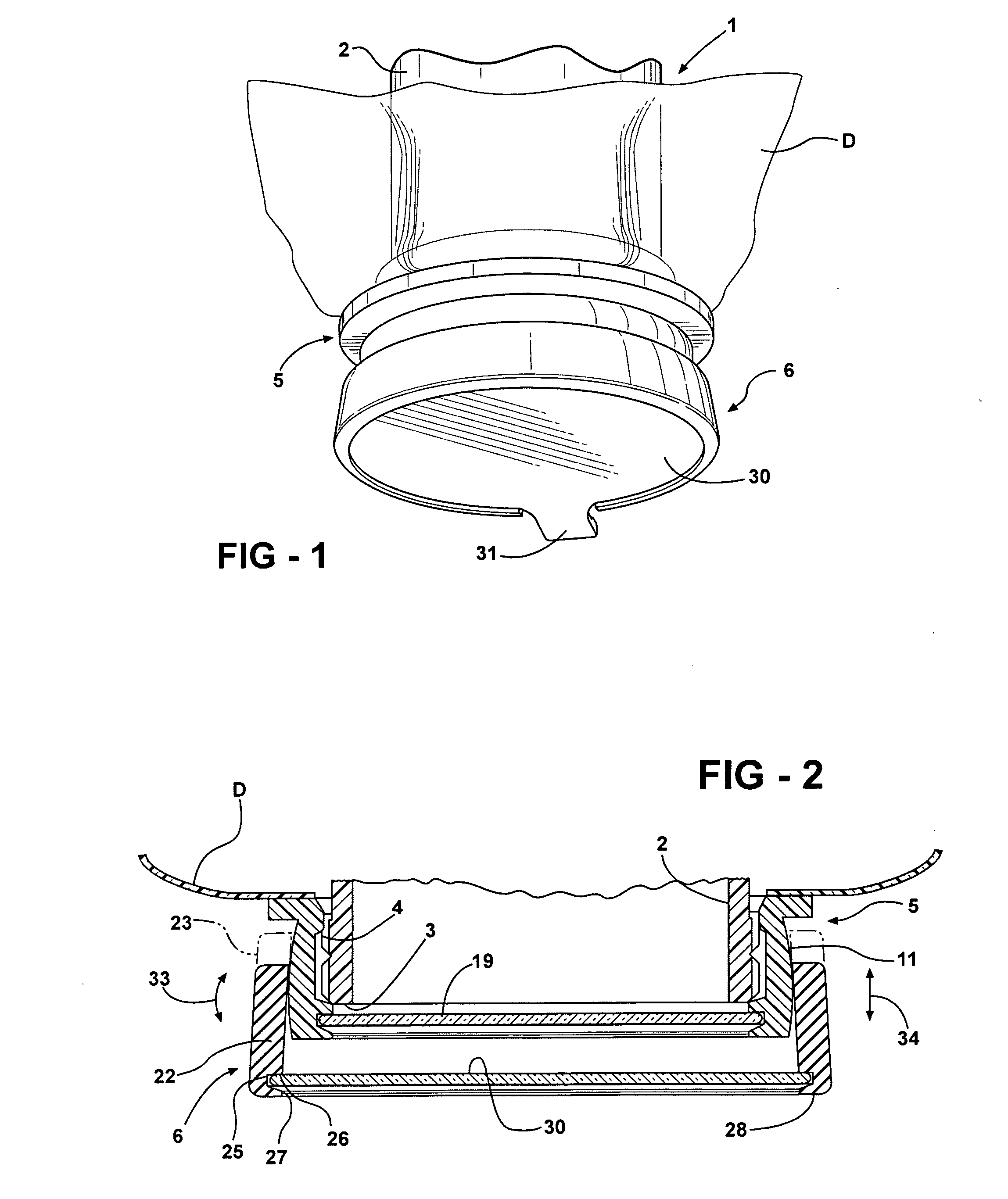
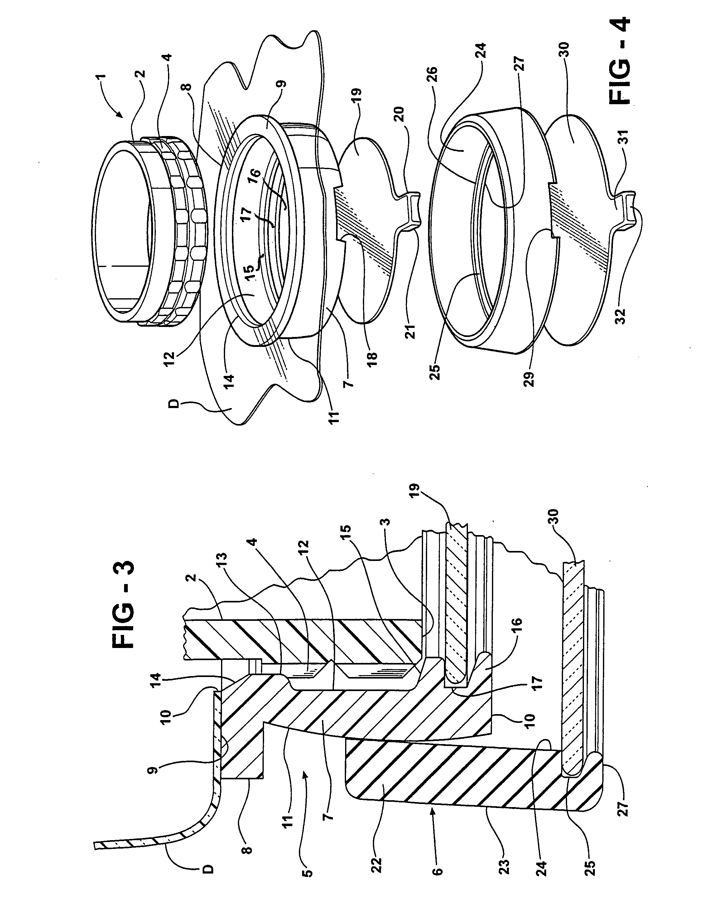
[0016] Apparatus constructed in accordance with the preferred embodiment of the invention is especially adapted for use with a surgical microscope of known construction having an objective lens housing or barrel 1 which extends beyond the microscope housing and contains objective lenses (not shown) through which light may pass from a source (not shown) of illumination through the housing to the surgical site, and thence, to the eyepiece or eyepieces (not shown) through which a surgeon and / or assistants may view the site. The housing 1 typically has a cylindrical wall 2 having a free end 3 encircled by circumferentially spaced, longitudinally extending ribs 4 which project radially outwardly. The apparatus described thus far is conventional and forms no part of the invention except for the manner in which it cooperates with apparatus yet to be described.

[0017] The preferred embodiment of the invention comprises a first annular retainer 5 and a second annular retainer 6. The first re...


PUM


Abstract

A protective cover for removable attachment to an objective lens housing of a draped surgical microscope has a primary, annular retainer of such size as to encircle and engage the lens housing. The retainer has an external frusto-spherical surface and an internal surface capable of seating on and snugly engaging the lens housing. The retainer removably supports a transparent shield for protecting the lenses in the lens housing. A secondary annular retainer encircles the primary retainer and has an internal surface which seats on and is supported by the external surface of the primary retainer. The secondary retainer removably accommodates a second transparent shield forming a closure for the secondary retainer. The second retainer is axially, rotatably, and rockably adjustable relative to the primary retainer for minimizing the transmission of glare to the microscope.

Description

[0001] This invention relates to a surgical microscope lens protective cover assembly of the kind used in conjunction with sterile drapes which maintain a sterile field above a patient during the performance of an invasive surgical procedure. BACKGROUND OF THE INVENTION [0002] The use of a surgical microscope by a surgeon during an invasive surgical procedure is common. The surgical microscope conventionally includes an objective lens housing or barrel typically enclosed within a sterile drape constituted by a thin, plastic film. The drape conventionally has an opening therein through which the objective lens housing of the microscope projects so that the drape film does not interfere with the ability of the surgeon to maintain clear visibility of the surgical site. The opening through which the objective lens housing extends conventionally is provided with a seal so as to avoid the provision of a path adjacent the opening through which contamination may pass. Some of the known cons...

Claims


Application Information

Patent Timeline
Patent Type & Authority Applications(United States)
IPC IPC(8): A61B19/02A61B19/08G02B7/02G02B21/00
CPCG02B21/0012A61B46/10
Inventor WEAVER, RICHARDWRIGHT, JOSEPHSOKOLOWSKI, NATHAN
Owner TIDI CFI PROD
Why Eureka
Try Eureka