Suspension thrust bearing device

a thrust bearing and suspension technology, applied in the direction of elastic bearings, bearing rigid support, transportation and packaging, etc., can solve the problems of excessive frictional torque, local cracking or fracture, unacceptable stresses on the material, etc., and achieve the effect of avoiding the risk of accidental disassembly of the elements

Inactive Publication Date: 2005-04-28
AB SKF
View PDF12 Cites 35 Cited by
  • Summary
  • Abstract
  • Description
  • Claims
  • Application Information

AI Technical Summary

Benefits of technology

[0011] The present invention proposes a suspension thrust bearing tailored to various types of springs while retaining silent, reliable operation.
[0012] According to one embodiment, the suspension thrust bearing device includes a rolling bearing provided with two races and with rolling elements arranged between the races, and two caps each in contact with one race. One of the caps includes a circular flange and the other cap includes an axial portion provided with hooks intended for latching onto the flange. An axial space of height b remains between the said hooks and the said flange. One of the caps includes an operational part provided with a chamfer intended to facilitate latching with the other cap, with an axial surface of height A and of diameter D and with a substantially radial retention surface. The other cap includes an operational part provided with a chamfer intended to facilitate latching, with an axial surface of height c and with a substantially radial retention surface. The sum of the heights a+b+c is greater than 1.9% of the diameter D. It is thus possible to very significantly reduce the risk of malfunction of the thrust bearing due to excessive misalignment of the axes of the caps when mounting the spring.
[0020] In other words, the upper cap and lower cap generally include a device for mutual axial retention by means of clipping, making it possible to form an assembly which may be handled and transported without risk of accidental disassembly of the elements. The caps may also include sealing devices allowing the rolling bearing to be housed in a closed space isolated from external pollution such as splashing water and various contaminants. The assembly formed by the rolling bearing and the caps is arranged between the body of the vehicle and an upper part of the spring. It may bear on the body of the vehicle directly or by way of a cup or else a filtering elastic block. The spring, arranged around the damper, bears at its lower end on a support cup secured to the damper cylinder and, at its upper end, bears directly or indirectly on the lower cap. The spring is installed around the rod of the damper piston. The suspension thrust bearing thus allows the axial forces to be transmitted between the spring and the body of the vehicle.
[0021] The caps may be made of an injection-molded synthetic material, for example glass-fiber-reinforced nylon-6,6 polyamide. The upper cap and lower cap may be latched into place by positioning one of them concentrically over the other and exerting an axial force tending to bring them towards one another. The caps allow transmission of the axial forces between the raceways and the elements on which the thrust bearing bears, under good load distribution conditions.

Problems solved by technology

However, in many struts of recent design the springs have a complex shape and, after they have been fitted on the vehicle, exert an axial force which does not pass through the axis of the rolling bearing.
Since the caps are made of a relatively rigid synthetic material—often glass-fiber-reinforced nylon-6,6 polyamide—a large interference could cause unacceptable stresses on the material and local cracking or fractures.
After carrying out numerous tests, the Applicant noticed that when the two caps are disunited beyond a certain limit, the said caps do not generally return correctly into position, and local relative friction between the said caps subsequently occurs and this forms the basis of incorrect operation of the suspension thrust bearing with generation of noise and an excessive frictional torque.

Method used


Image

  • Suspension thrust bearing device
  • Suspension thrust bearing device
  • Suspension thrust bearing device

Examples


Embodiment Construction

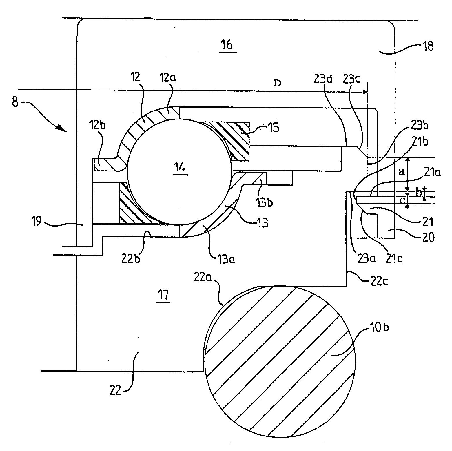
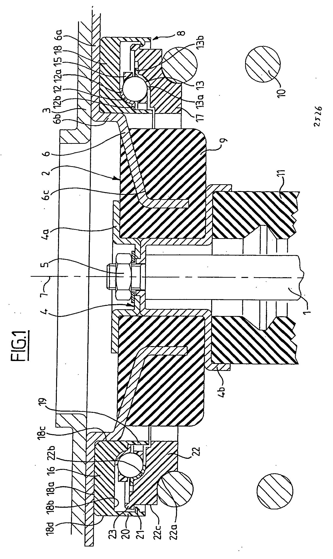
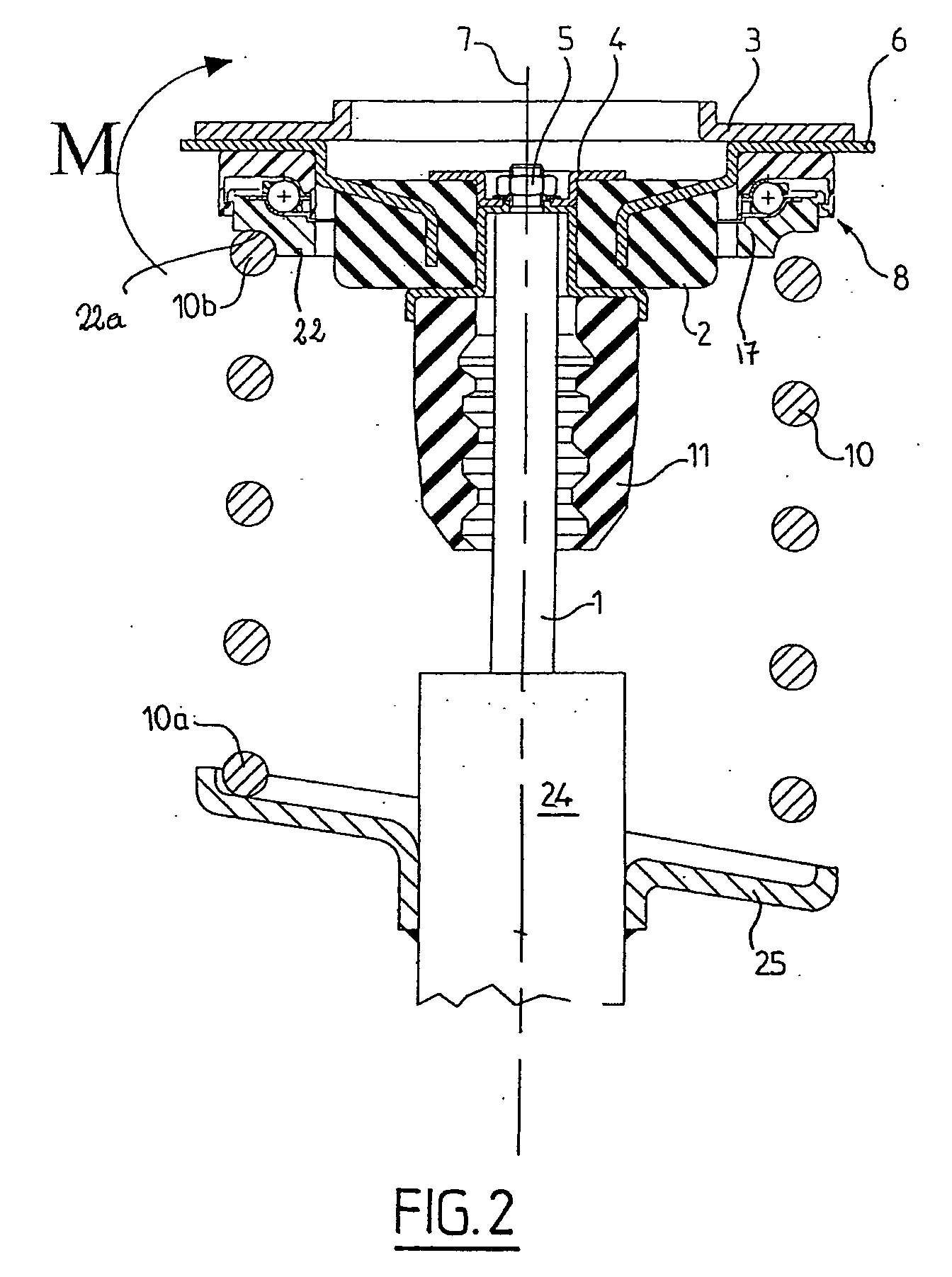
[0030] As can be seen in FIG. 1, the upper end of a damper includes a piston rod 1 connected by its upper end to an elastic support block 2 which bears in a seat-forming element of the chassis 3 and is secured to the latter.

[0031] The elastic support block 2 includes an annular inner connection element 4 made in two parts 4a and 4b, on which parts is mounted the end of the rod 1 of the damper piston by means of a nut 5, and an annular outer connection element 6 used for fastening to the chassis 3, all of these elements being centered around an axis 7. A thrust rolling bearing 8 is mounted in contact with the outer connection element 6. The elastic support block includes a rubber block 9 bonded to the surface of an inner part of the outer connection element 6 and clamped between the cup-shaped parts 4a and 4b of the inner connection element 4. An axial connection with vibration filtering is thus produced between the rod 1 and the chassis 3. The outer connection element 6 is fixed to...


PUM


Abstract

A suspension thrust bearing device includes a rolling bearing provided with two races and with rolling elements arranged between the races, and two caps each in contact with one race, one of the caps including a circular flange and the other cap including an axial portion provided with hooks intended for latching onto the said flange, which hooks leave an axial space of height b remaining between the said hooks and the said flange, one of the caps including an operational part provided with a chamfer intended to facilitate latching with the other cap, with an axial surface of height a and of diameter D and with a radial retention surface, and the other cap including an operational part provided with a chamfer intended to facilitate latching, with an axial surface of height c and with a radial retention surface, the sum of the heights a+b+c being greater than 1.9% of the diameter D.

Description

BACKGROUND OF THE INVENTION [0001] 1. Field of the Invention [0002] The present invention relates to the field of suspension thrust bearings used in particular in motor vehicles for the telescopic suspension struts of the steered wheels. [0003] 2. Description of the Relevant Art [0004] A suspension thrust bearing generally includes an upper race and a lower race between which are arranged rolling elements in the form of balls or rollers. A suspension thrust bearing is generally arranged in the top of the suspension strut, between a suspension spring and an upper element secured to the body of the vehicle. The spring of the suspension device is installed around the rod of the damper piston, the end of which is secured to an elastic support block. The suspension thrust rolling bearing allows rotational movement between the support cup for the spring, which may rotate, and the elastic support block, which is fixed to the body of the vehicle. The relative angular movement between the su...

Claims


Application Information

Patent Timeline
Patent Type & Authority Applications(United States)
IPC IPC(8): B60G15/06
CPCB60G15/068B60G2204/418F16C2326/05F16C19/10F16C43/04
Inventor DEBRAILLY, FRANCKPOULLE, THIERRY
Owner AB SKF
Why Eureka
Try Eureka