Combination wavelength multiplexer and wavelength stabilizer

Inactive Publication Date: 2005-04-28
OPTOVIA +1
View PDF9 Cites 23 Cited by
  • Summary
  • Abstract
  • Description
  • Claims
  • Application Information

AI Technical Summary

Benefits of technology

[0007] From a first apparatus aspect, the present invention is an arrangement for wavelength locking each of a plurality of radiation sources that generate separate wavelength output signals, the arrangement comprising a multiplexing / demultiplexing grating device, a plurality of radiation detectors, and a control device. The multiplexing / demultiplexing grating device receives the separate wavelength output signals from the plurality of radiation sources and generates a multiplexed wavelength output signal from the arrangement at a zero diffraction order output port of the grating device, and separate symmetric wavelength+δ and wavelength−δ output signals that are resolved at at least one separate predetermined location of a non-zero diffraction order area of the grating device for each radiation source. Each of the plurality of radiation detectors is coupled to receive a separate one of the symmetric wavelength+δ and wavelength−δ output signals from a separate one of the plurality of radiation sources, and to generate an output signal representing the magnitude of the received wavelength output signal. The control device responsive to output signals from each pair of radiation detectors that are coupled to receive the separate symmetric wavelength+δ and wavelength−δ output signals from a separate predetermined one of the plurality of radiation sources for generating a separate output control signal to each one of the plurality of radiation sources for locking the separate wavelength output signal thereof to a desired wavelength value.
[0008] From a second apparatus aspect, the present invention relates to a transmitter or amplifier pump source for use in an optical communication system comprising a plurality of radiation sources, and means for locking the wavelength of the radiation sources to the assigned value comprising a multiplexing / demultiplexing grating device, a plurality of radiation detectors, and a control device. Each of the plurality of radiation sources radiate light of a different assigned wavelength. The multiplexing / demultiplexing grating device receives the separate wavelength output signals from the plurality of radiation sources and generates a multiplexed wavelength output signal from the arrangement at a zero diffraction order output port of the grating device, and symmetric wavelength+δ and wavelength−δ output signals for each radiation source that are resolved at separate predetermined locations of a non-zero diffraction order of the grating device. Each of the plurality of radiation detectors is coupled to receive a separate one of the symmetric wavelength+δ and wavelength−δ output signals from a separate one of the plurality of radiation sources, and generates an output signal representing the magnitude of the received wavelength output signal. The control device is responsive to output signals from each pair of radiation detectors that are coupled to receive the separate wavelength+δ and wavelength−δ output signals from a separate predetermined one of the plurality of radiation sources for generating a separate output control signal to each one of the plurality of radiation sources for locking the separate wavelength output signal thereof to a desired wavelength value.
[0009] From a first method aspect, the present invention is a method of wavelength locking each of a plurality of radiation sources which generate different wavelength output signals. In the method, the wavelength output signals from the plurality of radiation sources are received in a multiplexing / demultiplexing grating device. The grating device is designed to generate a multiplexed wavelength output signal at a zero diffraction order output port of the grating device, and generate separate symmetric wavelength+δ and wavelength+δ output signals for each radiation source that are resolved at separate predetermined locations in a predetermined non-zero diffraction order of the grating device. Each of the resolved symmetric wavelength+δ and wavelength−δ output signals from the plurality of radiation sources is received by a separate one of a plurality of radiation detectors. Each radiation detector generates an output signal representing the magnitude of the received wavelength output signal. A control device is responsive to the output signals from each pair of radiation detectors that are coupled to receive the separate symmetric wavelength+δ and wavelength−δ output signals from a separate predetermined radiation source for generating therefrom a separate output control signal to each of the radiation sources for locking the wavelength thereof.
[0010] From a second method aspect, the present invention is a method of wavelength locking a plurality of wavelengths generated by a corresponding plurality of radiation sources of a transmitter or amplifier pump source in an optical communication system. In the method, the wavelength output signals from the plurality of radiation sources are received in a multiplexing / demultiplexing grating device for generating a multiplexed wavelength output signal at a zero diffraction order output port of the grating device, and generating separate symmetric wavelength+δ and wavelength−δ output signals for each radiation source that are resolved at separate predetermined locations of a predetermined non-zero diffraction order of the grating device. Each one of the symmetric wavelength+δ and wavelength−δ output signals from the plurality of radiation sources is received at a separate one of a plurality of radiation detectors, and an output signal is generated at each radiation detector representing the magnitude of the received wavelength output signal. Separate output control signals are generated by a control device in response to the output signals from each pair of radiation detectors that are coupled to receive the separate symmetric wavelength+δ and wavelength−δ output signals from a separate predetermined radiation source for locking the wavelength of each of the predetermined radiation sources.
[0011] The invention will be better understood from the following more detailed description taken with the accompanying drawings and claims.

Problems solved by technology

One problem with this arrangement is that the stabilization feedback is performed on multiplexed signals and is dependent on having signal modulation for the detection of which wavelength in the multiplexed signal is drifting.

Method used


Image

  • Combination wavelength multiplexer and wavelength stabilizer
  • Combination wavelength multiplexer and wavelength stabilizer
  • Combination wavelength multiplexer and wavelength stabilizer

Examples


first embodiment

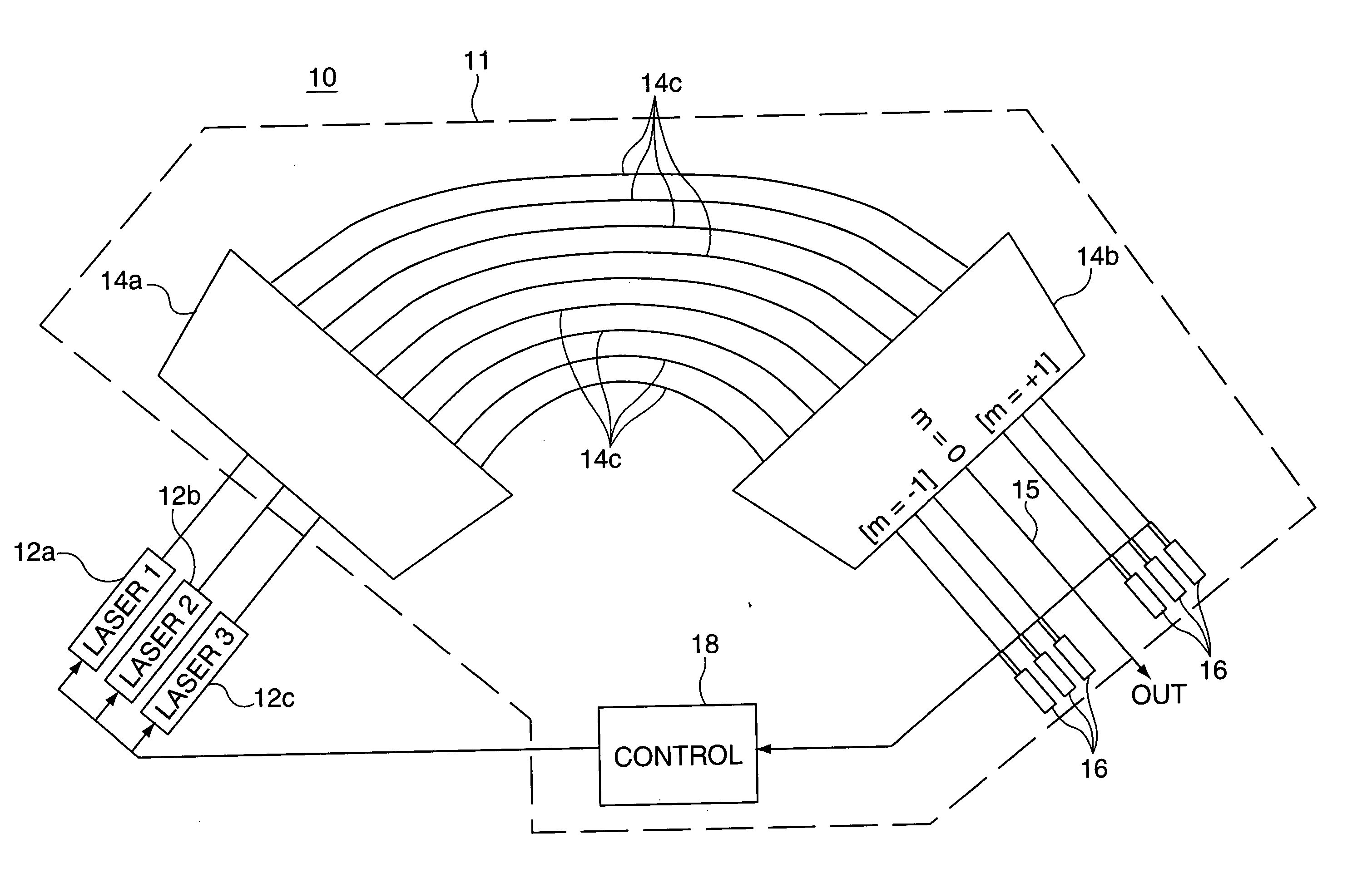
[0020] Referring now to FIG. 1, there is shown a general schematic diagram of a transmitter 10 including a plurality of radiation sources (LASER 1, LASER 2, LASER 3) 12a, 12b, and 12c and an optical wavelength locking arrangement (hereinafter wavelocker) 11 (shown within a dashed line area) in accordance with the present invention. The wavelocker 11 comprises a first Free Propagation Region (FPR) 14a, a second FPR 14b, an array waveguide section 14c formed from a plurality of different predetermined length waveguides, a plurality of either single or pairs of radiation detectors 16, and a control device 18. The radiation sources are shown as lasers 12a (LASER 1), 12b (LASER 2), and 12c (LASER 3). Each of the plurality of lasers 12a, 12b, and 12c are arranged to generate an output signal with a different predetermined wavelength. The output wavelength signals from the lasers 12a, 12b, and 12c are coupled to separate appropriate inputs of the first FPR 14a. The first and second FPRs 14...

second embodiment

[0032] Referring now to FIG. 7, there is shown a schematic diagram of a transmitter 40 comprising a plurality of radiation sources (LASER 1, LASER 2, LASER 3) (of which exemplary lasers 42a, 42b, and 42c are shown), and an exemplary optical wavelength locking arrangement (hereinafter wavelocker) 41 (shown within a dashed line area) in accordance with the present invention. The wavelocker 41 comprises a first Free Propagation Region (FPR) 44a, a second FPR 44b, an optical grating section formed from a plurality of different length waveguides 44c, a plurality of radiation detectors 46a, 46b, 46c, 46d, 46e, and 46f, a feedback loop 47 (shown as a dashed line), and a control device 48. Each of the plurality of lasers 42a, 42b, and 42c are arranged to generate a different predetermined wavelength output signal. The arrangement of the wavelocker 41 is especially useful when densely spaced output wavelength channels are generated by the lasers 42a, 42b, and 42c. The densely spaced output w...


PUM


Abstract

In an optical device, each of a plurality of radiation sources generates a separate different wavelength output signal to a wavelength locking device wherein a grating device receives the separate wavelength output signals from the plurality of radiation sources. The grating device generates a multiplexed wavelength output signal at a zero diffraction order output port thereof, and resolves separate symmetric wavelength+δ and wavelength−δ output signals at separate predetermined locations within at least one non-zero diffraction order thereof for each of the radiation sources. Each of a plurality of radiation detectors is coupled to receive a separate one of the symmetric wavelength+δ and wavelength−δ output signals and generate an output signal representing the magnitude of the received wavelength output signal. A control device is responsive to output signals from each pair of radiation detectors coupled to receive the separate symmetric wavelength+δ and wavelength−δ output signals from a specified predetermined radiation source for generating an output control signal appropriate to that radiation source for locking the wavelength thereof.

Description

CROSS REFERENCE TO RELATED APPLICATIONS [0001] This application is related to U.S. Ser. No. ______, entitled “DEVICES UTILIZING GRATINGS AND POWER TAPS WITH OPTIMIZED LOSS AND POWER SPLITTING CAPABILITIES” (Optovia 5), and has a common assignee and two common inventors with the present application and is being filed concurrently with the present application.FIELD OF THE INVENTION [0002] The present invention relates to optical systems utilizing transmitters and amplifier pump sources in which wavelengths generated by at least two radiation sources are multiplexed and individually locked in a grating based device. BACKGROUND OF THE INVENTION [0003] Wavelockers, devices used to maintain laser wavelengths, are extensively used in transmitters of telecommunication systems and can also be used to stabilize lasers used to pump amplifiers in such systems. Additionally, present day telecommunication amplifiers are requiring increasing levels of wavelength stable pump power that can be reali...

Claims


Application Information

Patent Timeline
Patent Type & Authority Applications(United States)
IPC IPC(8): G02B6/34
CPCG02B6/12016G02B6/4215G02B6/12021G02B6/12019
Inventor SQUIRES, EMILY M.KHAZAEI, HAMID R.
Owner OPTOVIA
Why Eureka
Try Eureka