Orthopedic hole filler

a technology of orthopedic and screw holes, applied in the field of bone implants, can solve the problems of substantially filling the screw hole, and achieve the effects of improving bone growth, increasing energy absorption, and increasing the amount of energy absorbed

Inactive Publication Date: 2005-04-28
RHODE ISLAND HOSPITAL
View PDF11 Cites 187 Cited by
  • Summary
  • Abstract
  • Description
  • Claims
  • Application Information

AI Technical Summary

Benefits of technology

[0008] The invention provides an apparatus and procedure for reducing stress risers in bones following orthopedic hardware removal from a bone. The apparatus reduces the risk of fractures associated with empty holes by altering the stress field around the hole. For example, the implant is biocompatible and is optionally bioresorbable, osteoconductive, and / or osteoinductive. The apparatus and procedure of the invention provide a bioresorbable implant that, as the implant breaks down, the implant is replaced by bone growth. An implant, such as a screw, acts as a filler in a bone hole. The implant is substantially cylindrical in shape. In one embodiment, the implant is screw-shaped having threads along substantially the entire length of the implant.
[0013] The device of the invention provides one or more of the following advantages compared to earlier methods. The biodegradable implant is effective as an implant in a weight bearing bone such as a femur, a tibia bone, or a non-weight bearing bone such as a forearm bone, e.g., a radius or ulna bone. The implant is applicable in any bone that has undergone hardware removal to leave an empty hole. Use of a growth factor in addition to the polymer composition of the implant stimulates and improves bone growth that eventually substantially completely replaces the implant. Filling bone holes with bioresorbable implants leads to at least 10%, 25%, 50%, 75%, or 90% increase in the amount of energy absorbed prior to failure. For example, a PLA hole filler led to 73% increase in the amount of energy absorbed prior to failure. Other higher percentages of increase in energy absorption are possible. Bones filled with the filler implant withstand a higher maximum torque than bone without the filler. The mean increase in the maximum torque that the bone having the filler is able to withstand increases by 10%, 20%, 30%, 50% or more. The bioresorbable implants additionally comprise characteristics that measurably improve upon the maximum torque to failure in a bone, energy to failure, fracture characteristics of bones. Growth factors and bone morphogenetic factors are optionally incorporated into or onto the device to enhance progressive bone ingrowth.

Problems solved by technology

The implants absorb water, which has the effect of causing the implant to swell, thereby substantially completely filling the screw hole.

Method used


Image

  • Orthopedic hole filler
  • Orthopedic hole filler
  • Orthopedic hole filler

Examples


Embodiment Construction

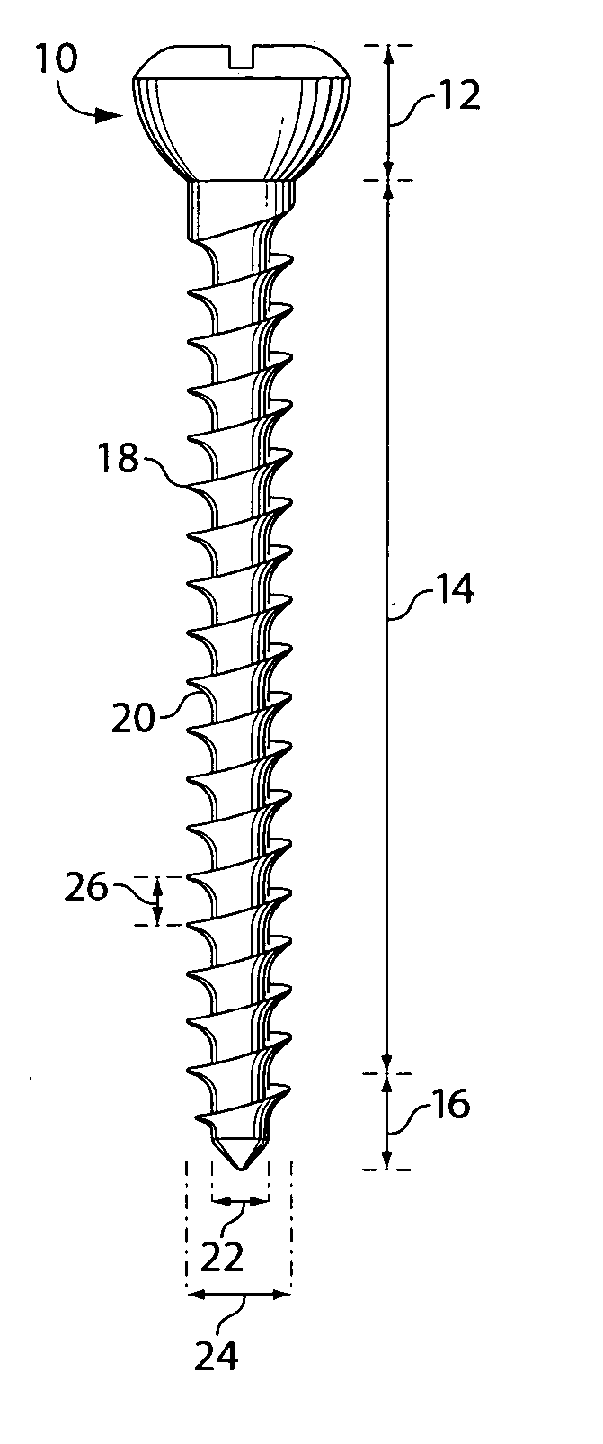
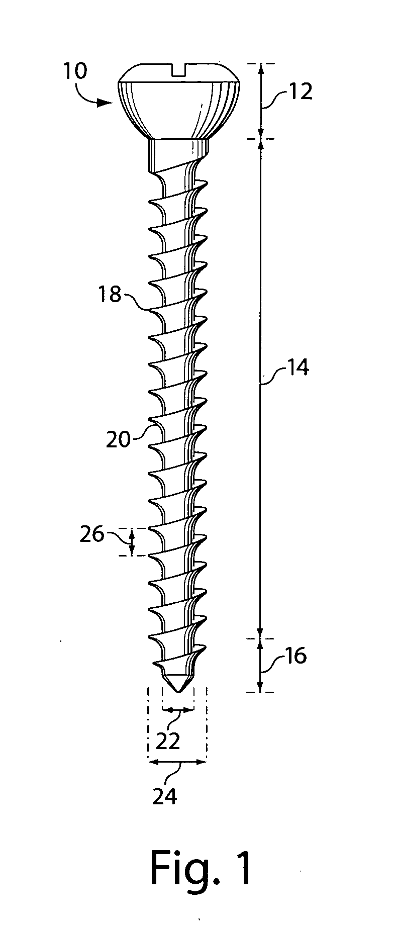
[0023] Empty holes left after removal of a first device, e.g., a metal pin or rod, are filled with a second device, e.g., a hole filler such as a bioresorbable implant or porous metallic implant which fill in empty holes left following metal hardware removal from the bones.

[0024] Embodiments of the invention are directed to an osteoconducfive, osteoinductive, bioresorbable, or biodegradable, implantable bone filler or screw used subsequent to removal of metal hardware that is present in a hole in the bone due to an orthopedic procedure. In one example, the implant has bioactive effects on ossification, such as recruitment of mesenchymal cells by growth factors in the implant (osteoinductive properties). Alternatively or in addition, the implant provides a three-dimensional framework for the ingrowth of capillaries and osteoprogenitor cells (osteoconductive properties).

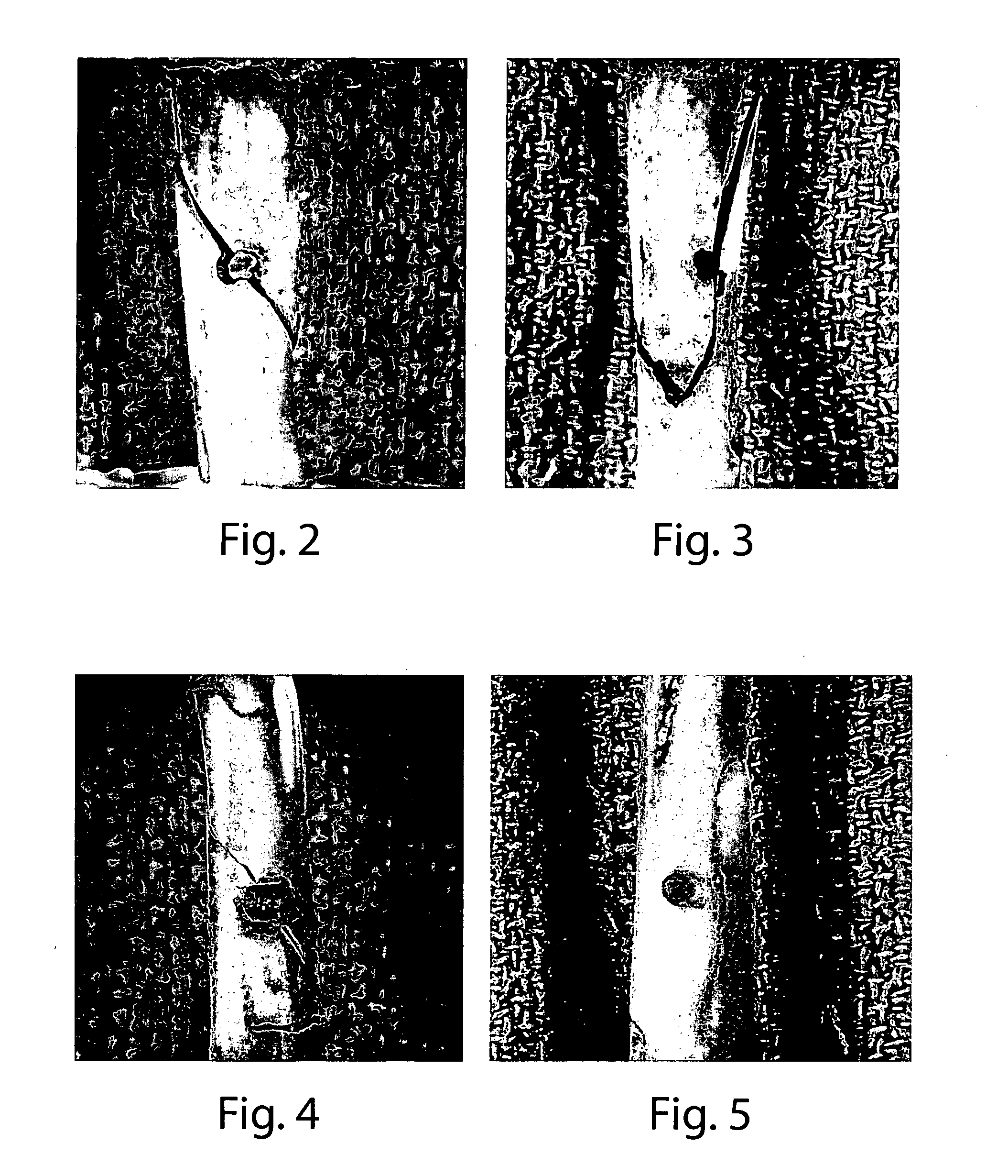
[0025] The apparatus of the invention alters the stress field around the hole by expanding, mechanically or chemic...


PUM


Abstract

A method of inhibiting formation of a stress riser in a bone is provided. The method is comprised of providing a bone having a first device and replacing the first device with a second device. Both the first device and the second device are substantially cylindrical, with the diameter of the second device being larger than that of the first device. Formation of a stress riser is inhibited in the presence of the second device.

Description

RELATED APPLICATIONS [0001] This application claims priority to provisional patent application serial number 60 / 492,461, filed on Aug. 4, 2003, the entire contents of which are hereby incorporated by reference.FIELD OF THE INVENTION [0002] The invention relates to bone implants. BACKGROUND OF THE INVENTION [0003] It is often necessary to fix a fractured or broken bone using inserts, for example, screws or other hardware, that are generally constructed of metals. The hardware inserted into the bone can be retained or removed accordingly. There is a significant rate of complications related to retained orthopedic hardware, particularly in high-level athletes in collision sports. Hardware removal can produce screw holes which are stress risers that weaken bone and can require prolonged athlete inactivation to prevent refracture. Refracture following hardware removal can be as high as 26% depending on hardware type and location, and the refracture often occurs through the residual empty...

Claims


Application Information

Patent Timeline
Patent Type & Authority Applications(United States)
IPC IPC(8): A61B17/00A61B17/56A61B17/86
CPCA61B17/863A61B17/8645A61B2017/564A61B2017/00004A61B17/866
Inventor ALFORD, J. WINSLOW
Owner RHODE ISLAND HOSPITAL
Why Eureka
Try Eureka