Device for flow restriction on a pump and pump device having such a device

A technology of limiting flow and controlling quantity, applied in the direction of pump device, fuel delivery of turbine/propulsion device, pump control, etc., which can solve the problems of lower pressure, lower excess volume, and higher pressure of filling and delivery pump.

Active Publication Date: 2016-02-03
ROBERT BOSCH GMBH
View PDF8 Cites 0 Cited by
  • Summary
  • Abstract
  • Description
  • Claims
  • Application Information

AI Technical Summary

Problems solved by technology

Here, the delivery volume and the pressure build-up via the pressure regulator valve are limited
However, this results in the disadvantage that when a large injection quantity is required, the excess volume at the pressure control valve and thus the pressure for filling the delivery pump is reduced, while when a small injection quantity is required at the pressure control valve The excess volume on the becomes larger and thus the pressure used to fill the delivery pump increases, although in this case no increase is required

Method used


Image

  • Device for flow restriction on a pump and pump device having such a device
  • Device for flow restriction on a pump and pump device having such a device

Examples


Embodiment Construction

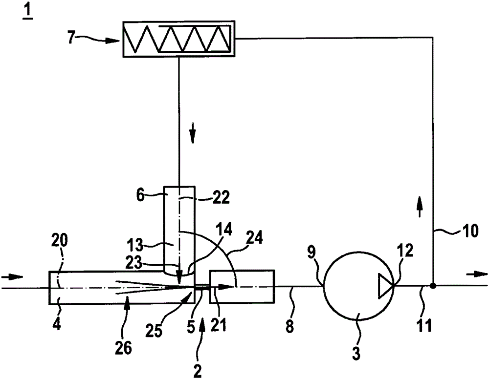
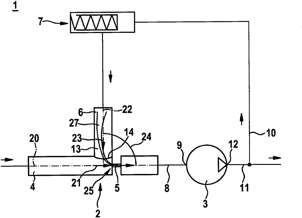
[0015] figure 1 A pump device 1 is shown with a device 2 for limiting the flow at the pump 3 . The pump 3 is here part of the pump device 1 , but not part of the device 2 . The device 2 for limiting the flow and the pump device 1 having the device 2 may in particular be used in a fuel injection system of a self-ignition internal combustion engine for compressing air. The pump 3 is designed here as a suction-throttle delivery pump. A preferred application of the pump arrangement 1 and the arrangement 2 is in a delivery pump for supplying fuel to a high-pressure pump of a fuel injection system having a common rail which stores diesel fuel under high pressure. However, the device 2 for flow limitation according to the invention and the pump device 1 according to the invention are also suitable for other applications.

[0016] The device 2 has an inlet channel 4 on the suction side of the pump 3 and likewise a control channel 6 on the suction side of the pump 3 , said inlet cha...


PUM


Abstract

A device (2) for restricting the throughflow quantity at a pump (3), in particular at a suction-throttled delivery pump for fuel injection systems of air-compressing, self-igniting internal combustion engines, has a feed channel (4) on the suction side of the pump (3), which feed channel (4) is connected on an outlet side (8) to an inlet (9) of a pump (3), a cut-off channel (6) which can be connected on its inlet side (10) at least indirectly to an outlet (12) of the pump (3) and which opens on its outlet side (13) laterally at an opening point (14) into the feed channel (4), and a pressure control valve (7) which is arranged in the cut-off channel (6). Furthermore, a throttle (5) is provided which is arranged in the feed channel (4) between the opening point (14) and the outlet side (8) of the feed channel (4). A transverse flow is caused at the opening point (14) by a cut-off quantity which is discharged via the cut-off channel (6), which transverse flow is superimposed with a main flow through the feed channel (4). As a result, a lateral incident flow of the throttle (5) can be achieved, as a result of which the effective throttle diameter is reduced. A given pressure difference at the pump (3) can therefore be reduced. Furthermore, Furthermore, a pump arrangement (1) with the pump (3) and the device (2) for restricting the throughflow quantity is disclosed.

Description

technical field [0001] The invention relates to a device for flow limitation on pumps, in particular on suction-restricted delivery pumps, and to a pump device having such a device. In particular, the invention relates to the field of fuel injection devices for air-compressed self-ignition internal combustion engines. Background technique [0002] A high-pressure pump for a fuel injection system of an internal combustion engine is known from DE 10 2004 028 999 A1. The known high-pressure pump has at least one pump element with a pump piston that is driven in a stroke movement and is movably guided in a cylinder bore of the pump housing part, in which the pump piston delimits A pump studio. The pump working chamber can be filled with fuel via an inlet valve during the suction stroke of the pump piston. In this case, the pump working chamber is connected to the delivery pump via a fuel inlet channel extending in the pump housing. [0003] It is conceivable for the delivery...

Claims


Application Information

Patent Timeline
Patent Type & Authority Patents(China)
IPC IPC(8): F04B23/08F04B23/14F04B49/24F04F5/10F02C7/236F04C14/24
CPCF04B23/08F04B23/14F04B49/24F04F5/10
Inventor C·朗根巴赫
Owner ROBERT BOSCH GMBH
Why Eureka
Try Eureka