
Computer system that a plurality of computers share a storage device

a computer system and storage device technology, applied in the direction of unauthorized memory use protection, input/output to record carriers, instruments, etc., to achieve the effect of reducing the access load on the storage device and eliminating delays

Inactive Publication Date: 2005-04-28
HITACHI LTD
View PDF14 Cites 50 Cited by
  • Summary
  • Abstract
  • Description
  • Claims
  • Application Information

AI Technical Summary

Benefits of technology

[0010] In this case, apparatuses (hereinafter referred to as node devices) such as cashe devices and gateway devices are often placed between the computers and the storage devices for the purposes of reduction in the access load on the storage devices and the elimination of delays.

Problems solved by technology

Conventional methods have problems described below, when a system is assumed in which logical units of storage devices assigned in units of users (enterprises, employees of the enterprises and the like) are used in any computers connected to any networks via the aforementioned node devices.
In the case where a node device is placed, since identification information of a computer used by a user is not sent to the storage devices (information identifying the node device is sent to the storage devices), the storage devices and the routers cannot perform access control, using the identification information of the computer used by the user.

Method used


Image

  • Computer system that a plurality of computers share a storage device
  • Computer system that a plurality of computers share a storage device
  • Computer system that a plurality of computers share a storage device

Examples


first embodiment

[0032] Hereinafter, the present invention will be described with reference to the accompanying drawings and the like. Referring to FIGS. 1 to 7, a description will be made of the present invention. It goes without saying that the present invention is not limited to embodiments described below.

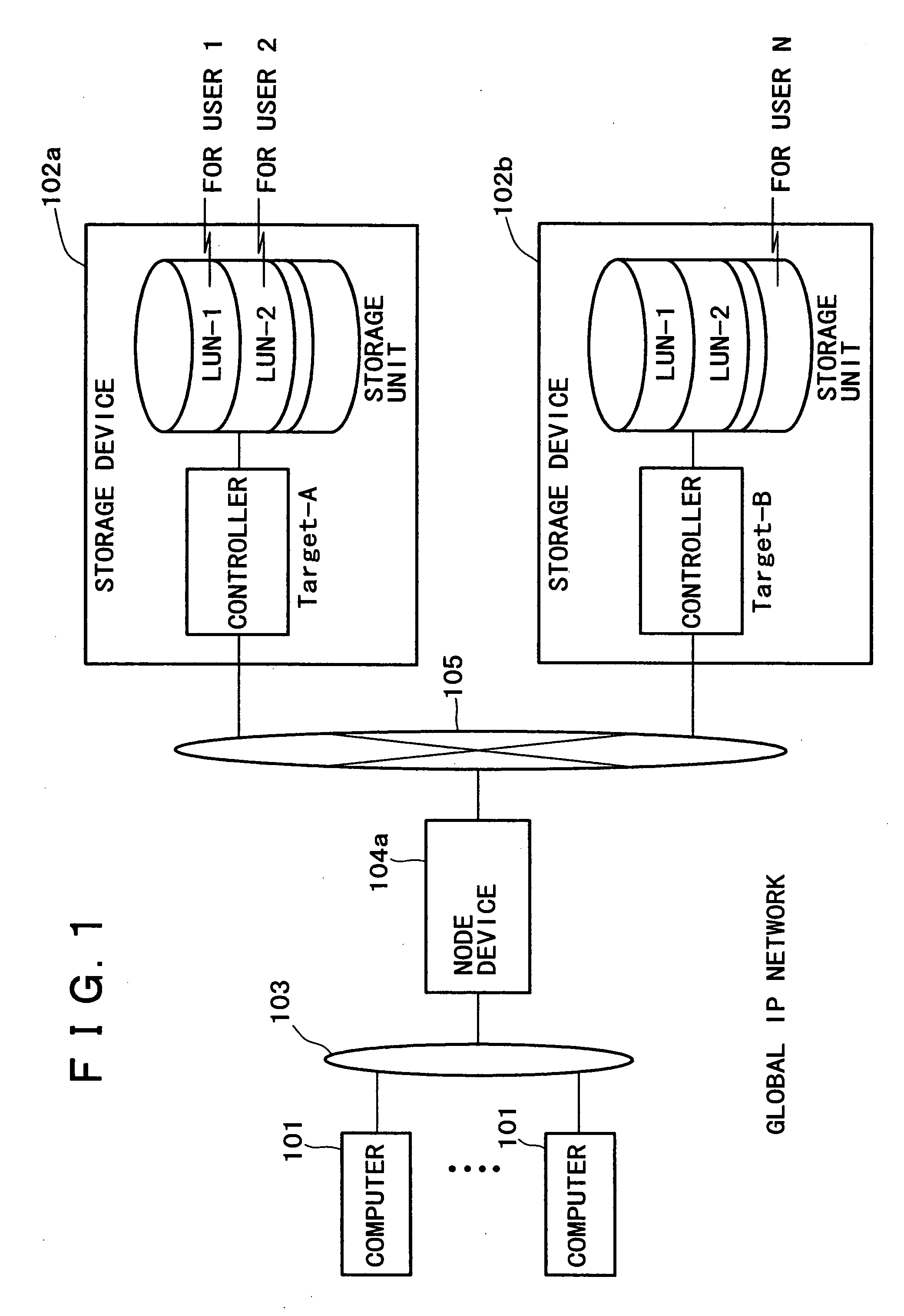
[0033]FIG. 1 is a drawing showing a sample configuration of a computer system to which the first embodiment is applied. The computer system includes computers 101, storage devices 102, a node device 104, and IP networks 103 and 105 that mutually connect them. Here, the IP networks refer to communication networks using internet protocols; their physical components (copper wire, optical fiber and the like) are not limited. IP networks 103 and 105 may be the same or different in configuration.

[0034] The computers 101 are used by users. Drivers and the like (hereinafter referred to as iSCSI drivers) that can process iSCSI protocols (particularly iSCSI initiator protocols) are incorporated in an op...

second embodiment

[0123] Although the node device 104 is single in the above description, a plurality of node devices 104 may exist. In the present embodiment, a central management server 106 described in a second embodiment may be provided. In this case, when the relay module 140 of the node device 104 uses the registration module 170 and the management module 120 of the central management server 106, the node device 104 and the central management server 106 perform the sending and receiving of packets through the IP network 105.

[0124] Next, a second embodiment will be described with reference to FIGS. 8 to 10.

[0125]FIG. 8 is a drawing showing a sample configuration of a computer system to which the second embodiment is applied.

[0126] In the present embodiment, a data center performs the service (hereinafter referred to as remote backup service) of reproducing data stored in a storage device 102 in a remote storage device 102. A storage device 102 mainly used is referred to as a main storage devic...


PUM


Abstract

A computer system includes: means for centrally managing user identification names and passwords that are assigned to users, target names of storage devices, addresses, and logical units; means for acquiring target names of storage devices and logical unit names from the user identification names and passwords; means for obtaining the addresses of the storage devices from the user identification names, passwords, and target names; and means for dynamically creating access control information of the logical units for each session in iSCSI session establishment processing.

Description

BACKGROUND OF THE INVENTION [0001] Field of the Invention [0002] The present invention relates to technology for sharing storage devices among a plurality of computers. More particularly, the present invention relates to technology for assuring the security of a system by the authentication of users when a plurality of computers use storage devices. [0003] In recent years, the iSCSI standards are being established as technology for using storage devices through networks. [0004] iSCSI (Internet SCSI) is protocol standards for sending and receiving SCSI (Small Computer System Interface) commands and data that have been conventionally used for data communication between computers and storage devices through networks using IP protocol for the Internet. With iSCSI, a computer issuing commands is referred to as an initiator, and a storage device receiving the initiator commands is referred to as a target. An initiator and a target are provided with an identifier called an initiator name a...

Claims


Application Information

Patent Timeline
IPC IPC(8): G06F12/14G06F3/06G06F15/16G06F15/167G06F17/30G06F21/62H04L29/08H04L29/12
CPCH04L29/12169H04L29/12594H04L29/12858H04L67/1097H04L61/3015H04L61/6031H04L61/1576H04L61/4552H04L2101/631H04L61/30
Inventor KOBAYASHI, IKUKOKIMURA, SHINJI
Owner HITACHI LTD
Learn More