System and method for locating an anomaly ahead of a drill bit

Inactive Publication Date: 2005-05-05
SHELL OIL CO
View PDF21 Cites 45 Cited by
  • Summary
  • Abstract
  • Description
  • Claims
  • Application Information

AI Technical Summary

Problems solved by technology

While currently available techniques are capable of detecting the presence of an anomaly, they are not capable of determining the location of the anomaly with sufficient depth or speed, they are not capable of detecting an anomaly at a sufficient distance ahead of a bit or bottom hole assembly.
As set forth above, the depth of investigation facilitated by the tool is li

Method used


Image

  • System and method for locating an anomaly ahead of a drill bit
  • System and method for locating an anomaly ahead of a drill bit
  • System and method for locating an anomaly ahead of a drill bit

Examples


Embodiment Construction

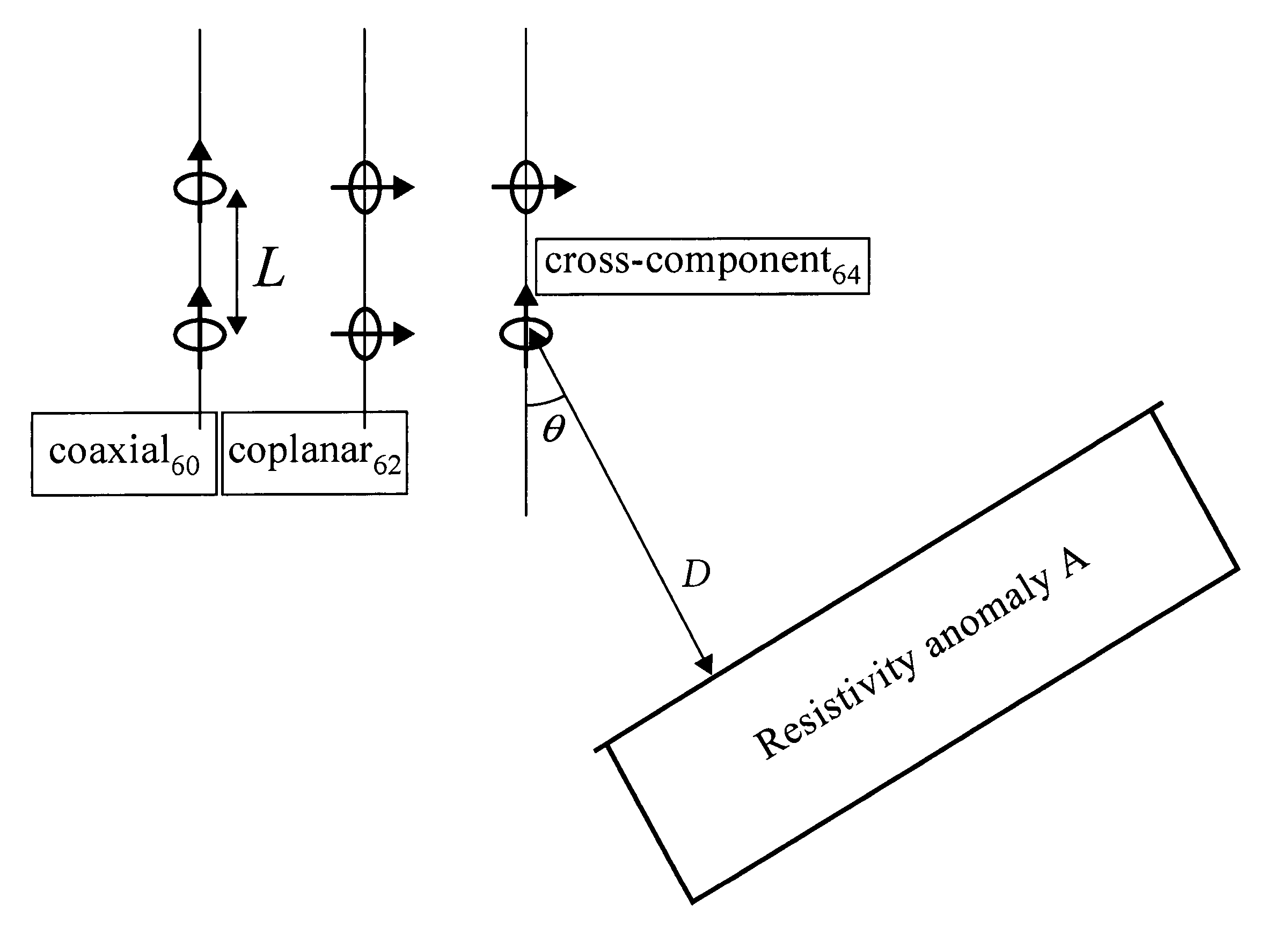
[0027] Embodiments of the invention relate to a system and method for determining distance and direction to an anomaly in a formation within a wellbore. Both frequency domain excitation and time domain excitation have been used to excite electromagnetic fields for use in anomaly detection. In frequency domain excitation, a device transmits a continuous wave of a fixed or mixed frequency and measures responses at the same band of frequencies. In time domain excitation, a device transmits a square wave signal, triangular wave signal, pulsed signal or pseudo-random binary sequence as a source and measures the broadband earth response. Sudden changes in transmitter current cause signals to appear at a receiver caused by induction currents in the formation. The signals that appear at the receiver are called transient responses because the receiver signals start at a first value and then decay or increase with time to a constant level. The technique disclosed herein implements the time do...


PUM


Abstract

A method and a system are provided for allowing determination of a distance from a tool to anomaly ahead of the tool. The apparatus for performing the method includes at least one transmitter and at least one receiver. An embodiment of the method includes transmitting electromagnetic signals from the at least one transmitter through the formation surrounding the wellbore and detecting voltage responses at the at least one receiver induced by the electromagnetic signals. The method includes calculating apparent conductivity or apparent resistivity based on a voltage response. The conductivity or resistivity is monitored over time, and the distance to the anomaly is determined from the apparent conductivity or apparent resistivity values.

Description

CROSS-REFERENCE TO RELATED APPLICATION [0001] The present application is a continuation-in-part of U.S. application Ser. No. 10 / 701,735 filed on Nov. 5, 2003, which is incorporated herein by reference. Applicants therefore, claim priority based on the filing date of U.S. application Ser. No. 10 / 701,735.STATEMENT REGARDING FEDERALLY SPONSORED RESEARCH OR DEVELOPMENT [0002] Not applicable. FIELD OF THE INVENTION [0003] The present invention relates to a method and system for locating an anomaly and in particular to finding the location of a resistive or conductive anomaly in a formation surrounding a borehole in drilling applications. BACKGROUND OF THE INVENTION [0004] In logging while drilling (LWD) geo-steering applications, it is advantageous to detect the presence of a formation anomaly ahead of or around a bit or bottom hole assembly. There are many instances where “Look-Ahead” capability is desired in LWD logging environments. Look-ahead logging is to detect an anomaly at a dist...

Claims


Application Information

Patent Timeline
IPC IPC(8): G01V3/30
CPCG01V3/28G01V3/30
Inventor BANNING, ERIKHAGIWARA, TERUHIKOOSTERMEIER, RICH
Owner SHELL OIL CO
Why Eureka
Try Eureka