Manufacture of LPRF device wake up using wireless tag

a wireless tag and lprf technology, applied in the field of wireless transceivers, can solve the problems of increasing radio traffic and interference, reducing the battery life of the device, and most known methods that do not address the self-configuration of the wireless node, so as to increase the range and increase the sensitivity

Inactive Publication Date: 2005-05-05
GOOGLE LLC
View PDF90 Cites 129 Cited by
  • Summary
  • Abstract
  • Description
  • Claims
  • Application Information

AI Technical Summary

Benefits of technology

[0014] In additional features of preferred embodiments, the second receiver provides the electronic signal by toggling a line connecting the second receiver with the LPRF communications component, and the LPRF communications device is programmed to power down when no longer actively transmitting or receiving. The second receiver provides power to the voltage regulators supplying power to the LPRF communications device causing it to power up or “boot up.” The second receiver may be passive, i.e., have no energy source; however, the second receiver preferably includes a battery to increase its sensitivity and, thus, significantly increase the range within which it may detect a transmission over the range that it otherwise would have without use of an energy source.

Problems solved by technology

However, most known methods do not address self-configuration of wireless nodes for the formation and maintenance of efficient network topology.
Known methods of ad hoc network organization also require nodes to regularly transmit network information to all other nodes in the network, which results in increased radio traffic and interference.
Increased radio interference inhibits the formation and maintenance of ad hoc networks having a large number of nodes and requires nodes to transmit at a greater power, which reduces their battery life.
However, while Bluetooth radio technology is an ad hoc networking solution for personal data applications, it provides for only a limited number of communication channels, thereby restricting the number of Bluetooth devices that can communicate over an ad hoc network at any given time.
However, existing wireless data network technologies are not well suited to asset tracking, which involves a large number of network nodes (e.g., hundreds or even thousands).
Furthermore, existing wireless technologies are cost prohibitive, are prone to radio frequency (RF) interference, and consume a large amount of electrical power.
Another obstacle to widespread implementation of the use of standards based radios, such as Bluetooth radios, especially in asset-tracking applications, is the limited life of the radio due to its power consumption.

Method used


Image

  • Manufacture of LPRF device wake up using wireless tag
  • Manufacture of LPRF device wake up using wireless tag
  • Manufacture of LPRF device wake up using wireless tag

Examples


example 1

Tagged Luggage System

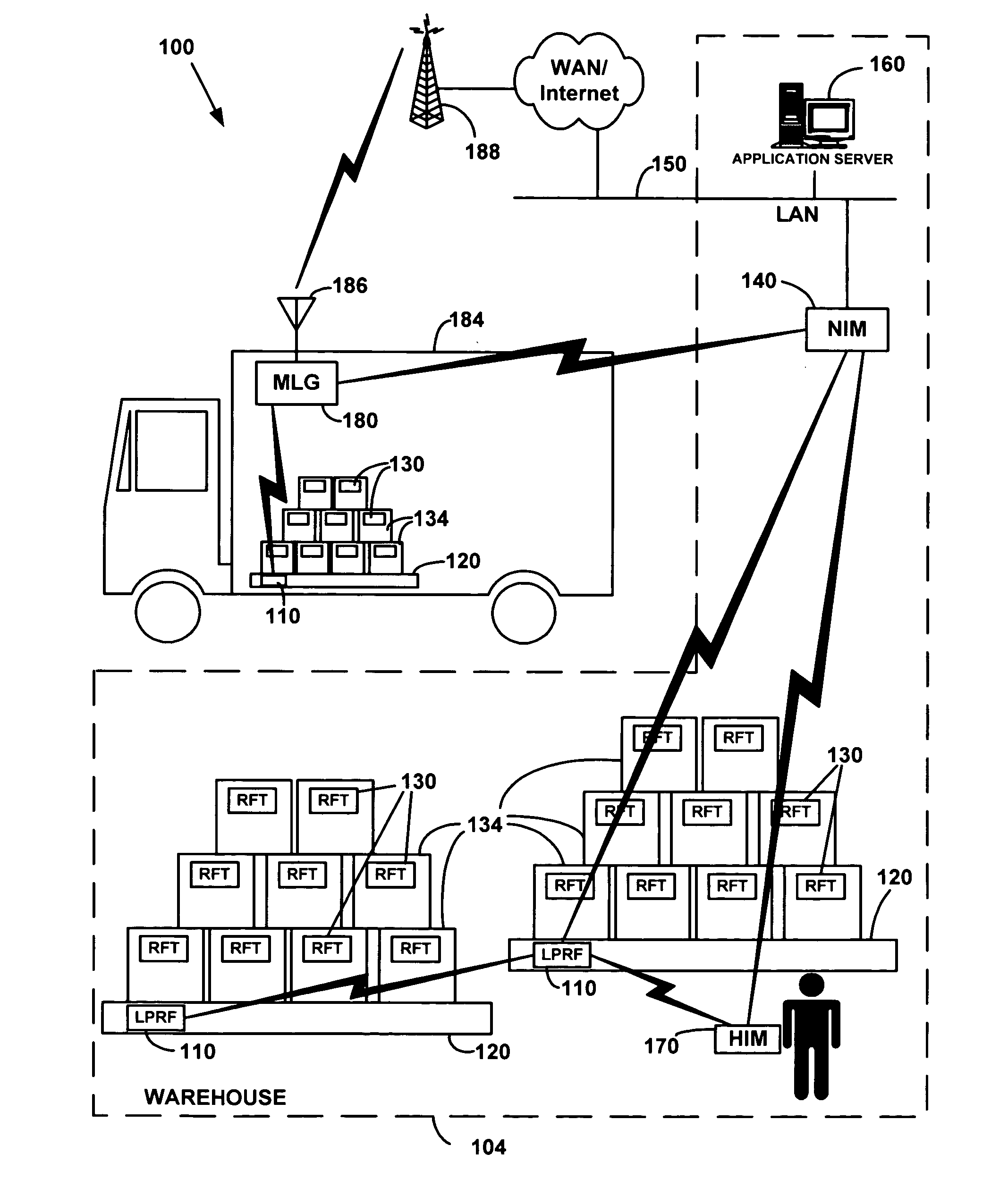
[0150] When a passenger checks in at the airport a Wireless Tag is attached to each item of the passenger's luggage. A corresponding Wireless Tag identifying the passenger is provided to the passenger to verify his / her identity at the destination baggage pickup location. A Wireless Reader Tag near the check-in counter detects and logs the Wireless Tags for the luggage in association with the passenger's Wireless Tag and related information into the asset-tracking system. The asset-tracking system downloads a profile into each of the Wireless Tags as identified by the Wireless Reader Tag at the check-in counter. The profiles are in the format: [0151] :Tag_Type:Airline_Name:Passenger_Class:Origin_and_Destination:Flight_No:Tag_Status:passenger_id

An example of the profile for the passenger's Wireless Tag is: [0152] :passenger:Delta_Airlines:First_Class:ATL-SEA:FLT-490:check-in:45567788KDKO8

while an example of the profile for the luggage Wireless Tag is: [0153] ...

example 2

Warehouse / Retail System

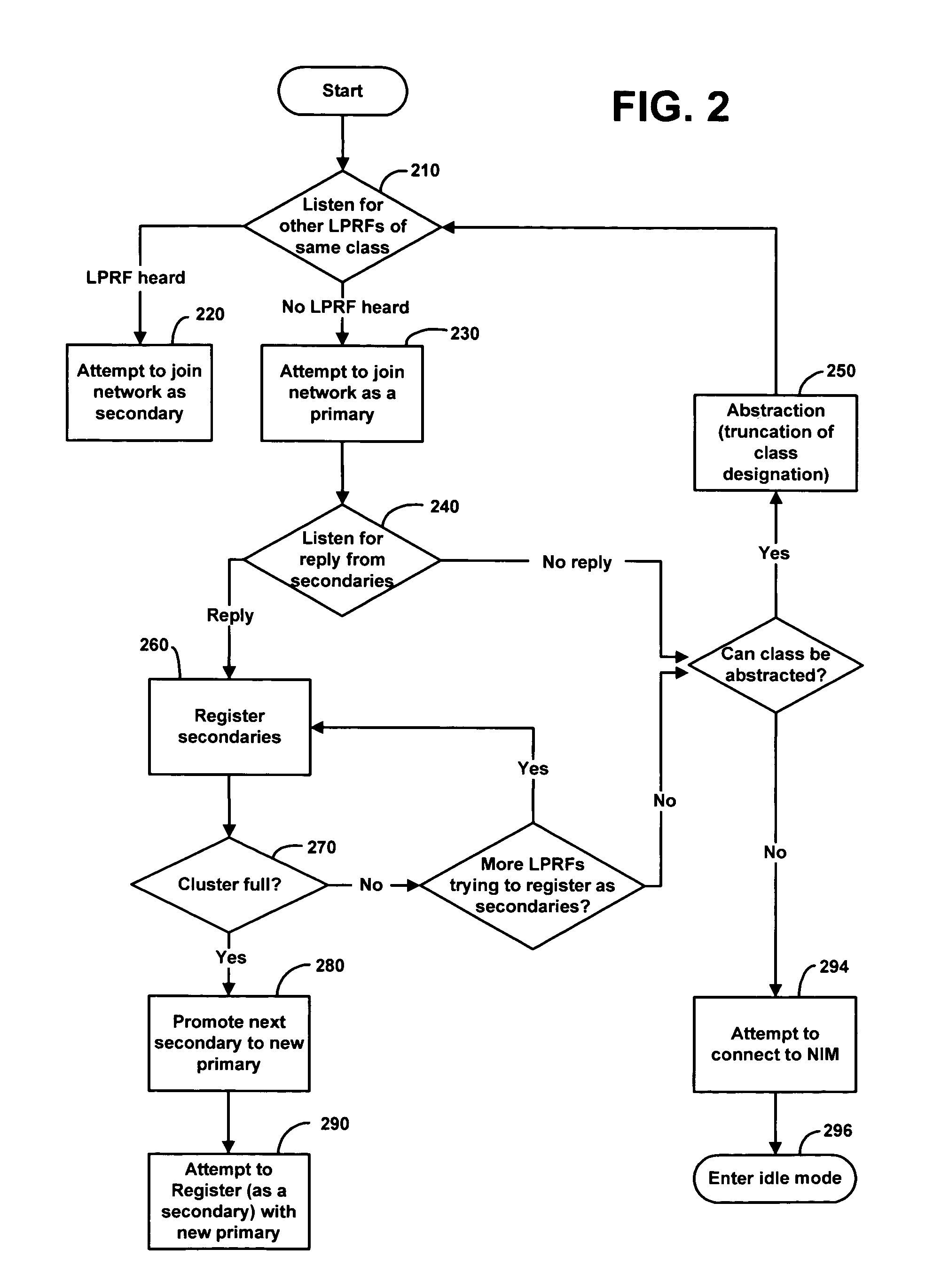
[0156] A warehouse store such as Costco carries hundreds of brands of products. Nevertheless, all products need to be inventoried on a real-time basis. In accordance with the present invention, a Wireless Reader Tag is attached to each pallet of goods and assigned a class designation that denotes the manufacturer of goods on that pallet (e.g., Pillsbury, Sony, Kellogg's, etc.). Each Wireless Reader Tag may also include in its class designation or profile, information about the goods on the pallet. Each boxes on the pallet carries a Wireless Tag that is read by the Wireless Reader Tag of the pallet. On demand, each Wireless Reader Tag gathers information about the Wireless Tags on its pallet and relays the information back to the asset-tracking application server. At any given time, an employee of the warehouse store can inventory goods of a selected manufacturer by sending a query that will be received only by Wireless Reader Tags of the selected class corres...

example 3

Shipping Containers Tracking System

[0157] Containers full of material shipped via rail or ship can be received and logged into a yard by manufacture based on class information stored on Wireless Reader Tags. The Wireless Reader Tags form a network with other containers from a particular manufacturer and allow quick and efficient tracking of containers. Messages directed to a selected class will not affect the battery life of Wireless Reader Tags of other classes because only Wireless Reader Tags of the selected class will wake up from standby to receive the messages and process the queries. The manufacturer classes can be divided into categories and subcategories, thereby further collectively reduce battery consumption and radio interference.


PUM


Abstract

A method is disclosed for manufacturing a wireless transceiver (5008) having a low power radio frequency (LPRF) component (5010) that powers down to conserve energy and powers up in response to a signal; and a second receiver (5014) that provides the signal via line (5018) in response to receipt of a radio frequency broadcast. The broadcast is targeted to activate particular transceivers by including in the broadcast identifications such as class designations, in which case the transceivers power up and form networks. A transceiver may include one or more identifications and may include a unique identification of the transceiver itself. The LPRF component is a Bluetooth radio, but the overall transceiver itself only draws about 10 to 15 μA while actively awaiting and screening for a targeted broadcast.

Description

CROSS-REFERENCE TO RELATED APPLICATIONS [0001] This application is a continuation of Twitchell international patent application Ser. No. PCT / US03 / 14987, titled LPRF DEVICE WAKE UP USING WIRELESS TAG, published in English, which was filed on May 14, 2003, and which application is a nonprovisional of, and claims priority under 35 U.S.C. § 119(e) to, each of the following U.S. provisional patent applications: (1) Twitchell U.S. patent application Ser. No. 60 / 380,195, titled DYNAMIC OBJECT IDENTIFIER BASED NETWORK FORMATION, which was filed on May 14, 2002, abandoned, which is incorporated herein by reference; and (2) Twitchell U.S. patent application Ser. No. 60 / 380,670, titled LOW POWER RADIO FREQUENCY COMMUNICATIONS DEVICE WAKE UP USING OBJECT IDENTIFIERS AND WIRELESS TAGS, which was filed on May 16, 2002, abandoned, which is incorporated herein by reference; and which international patent application further is a continuation-in-part of, and claims priority under 35 U.S.C. §§ 119(e)...

Claims


Application Information

Patent Timeline
Patent Type & Authority Applications(United States)
IPC IPC(8): G01S5/14G01S19/03G01S19/21G06K7/00G06K17/00G06Q10/00G07C9/00H04B1/16H04L12/18H04L12/28H04L12/56H04L29/08
CPCG01S5/14G06K7/0008G06K7/10079G06K2017/0045G06Q10/06G07C9/00111H04L69/329H04W48/10H04W52/0225H04W84/18H04L67/2819H04L67/14H04L67/28H04L12/189G07C9/28Y02D30/70H04L67/564H04L67/56
Inventor TWITCHELL, ROBERT W. JR.
Owner GOOGLE LLC
Why Eureka
Try Eureka