Lens structure of optic mouse

a mouse and lens structure technology, applied in the field of optic mouse, can solve the problems of high cost, high cost of parts themselves, troublesome and costly process of parts, etc., and achieve the effect of enhancing the performance of the optic mouse, reducing diffraction and deterioration

Inactive Publication Date: 2005-05-05
UNITY OPTO TECH CO LTD
View PDF3 Cites 24 Cited by
  • Summary
  • Abstract
  • Description
  • Claims
  • Application Information

AI Technical Summary

Benefits of technology

[0008] As such, the light emitter and the optic sensor are integrated in the single circuit chip, while the lens module is constructed and arranged to shorten an optic path for a light beam transmitting from the light emitter to the optic sensor whereby the light beam can travel in a more concentrated manner with reduced diffraction and deterioration thereof. Thus, performance of the optic mouse is enhanced.

Problems solved by technology

This is a troublesome and costly process for the parts must be precisely positioned and assembled to realize detection of the light beam traveling along the optic path between the LED 62 and the sensor 63 through all the optic elements mentioned above.
Also, costs of the parts themselves are high.
Thus, the conventional optic mouse suffers from poor performance and high costs and thus does not satisfy the demand of general consumers.

Method used


Image

  • Lens structure of optic mouse
  • Lens structure of optic mouse
  • Lens structure of optic mouse

Examples


Embodiment Construction

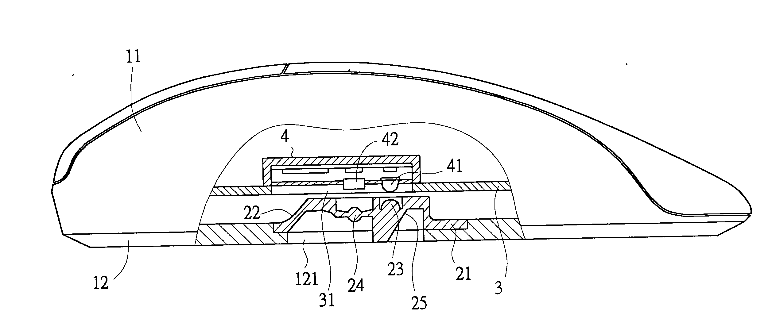
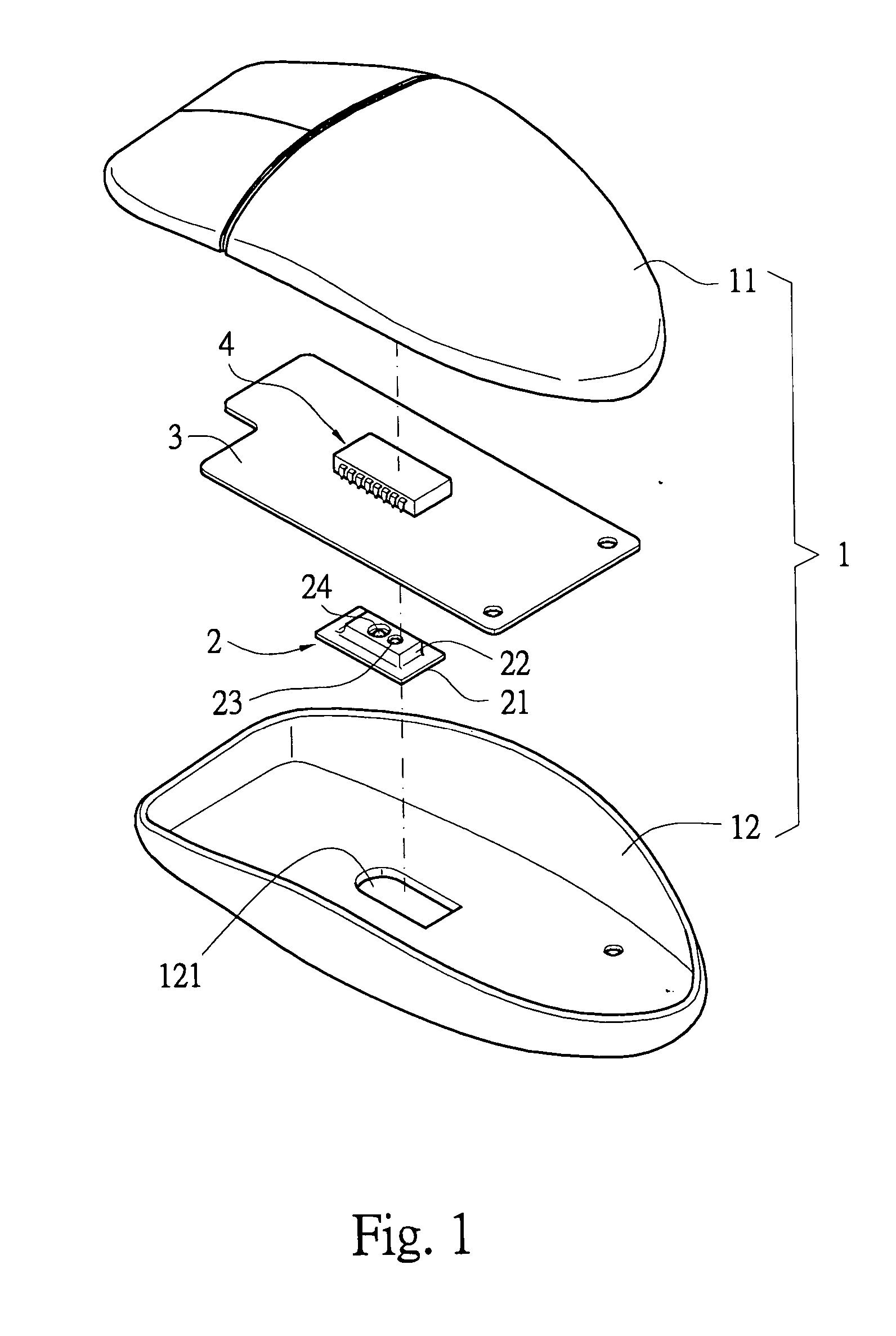
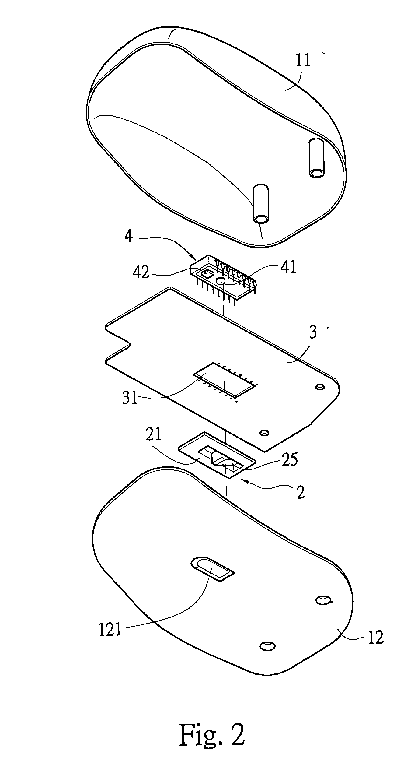
[0016] With reference to the drawings and in particular to FIGS. 1-3, an optic mouse constructed in accordance with the present invention comprises a mouse casing 1 to which a lens module 2 is mounted and a circuit board 3 to which a single circuit chip module 4 is mounted. The circuit board 3 is arranged inside the casing 1 to have the circuit chip module 4 positioned substantially corresponding to the lens module 2. The circuit chip module 4 comprises a light emitter or light source 41, such as a light-emitting diode (LED), and an optic sensor 42 integrated therewith. The lens module 2 is constructed and arranged to shorten an optic path for light traveling from the light emitter 41 to the optic sensor 42 whereby diffraction and deterioration of the optic signal during the travel of the light beam is alleviated and the performance of the optic mouse is enhanced.

[0017] The mouse casing 1 is comprised of a top casing member 11 and a bottom casing member 12 fixed to each other, defi...


PUM


Abstract

An optic mouse includes a casing and a circuit board fixed inside the casing. The casing has a bottom in which a first opening is defined for receiving and fixing a lens module. The lens module includes a support fixed to the first opening and forming a carrier that carries first and second lenses and a reflection portion located adjacent to the second lens and having a top connected to a bottom of the first lens. The circuit board includes a single circuit chip having integrated therewith a light emitter and an optic sensor positioned in correspondence to the first and second lenses, respectively. With the light emitter and the optic sensor integrated in the single circuit chip, the lens module is constructed and arranged to shorten an optic path for a light beam transmitting from the light emitter to the optic sensor whereby the light beam can travel in a more concentrated manner with reduced diffraction and deterioration thereof. Thus, performance of the optic mouse is enhanced.

Description

FIELD OF THE INVENTION [0001] The present invention generally relates to an optic mouse, and in particular to an optic mouse in which a light emitter and an optic sensor are integrated in a single circuit chip module and a lens module comprising optic elements arranged to shorten an optic path between the light emitter and optic sensor so as to alleviate undesired diffraction and diffusion of the light beam from the light emitter to the light sensor and thus enhancing performance of the optic mouse. BACKGROUND OF THE INVENTION [0002] An optic mouse employs optic techniques, including emission and detection of a light beam, to detect moving direction and speed of a computer mouse. An example of the conventional optic mouse is illustrated in FIGS. 5 and 6 of the attached drawings. The conventional optic mouse comprises a bottom plate 6 on which a top casing (not shown) is attached to define an interior space therebetween. A lens assembly 60 and a circuit board 61 are arranged in the i...

Claims


Application Information

Patent Timeline
Patent Type & Authority Applications(United States)
IPC IPC(8): G06F3/03G06F3/033G09G5/08
CPCG06F3/03543G06F3/0317
Inventor CHANG, WEIHUNG, HSIEN-YEHLU, YUAN-YING
Owner UNITY OPTO TECH CO LTD
Why Eureka
Try Eureka