Microscope magnification sensor

a technology of microscopy and magnification sensor, which is applied in the field of magnification systems, can solve problems such as margin of error in procedures

Inactive Publication Date: 2005-05-05
AMO MFG USA INC
View PDF13 Cites 40 Cited by
  • Summary
  • Abstract
  • Description
  • Claims
  • Application Information

AI Technical Summary

Benefits of technology

[0010] The present invention provides devices, systems and methods for scaling the size and/or position of a marker on a magnified image of an object. In preferred embodiments, the object is an eye that is undergoing laser eye surgery. The eye is viewed through a magnification system or microscope and an image of the eye is presented on a display. One or more markers are present on the im

Problems solved by technology

Sometimes this distance is held within 5 μm throughout ophtha

Method used


Image

  • Microscope magnification sensor
  • Microscope magnification sensor
  • Microscope magnification sensor

Examples


Embodiment Construction

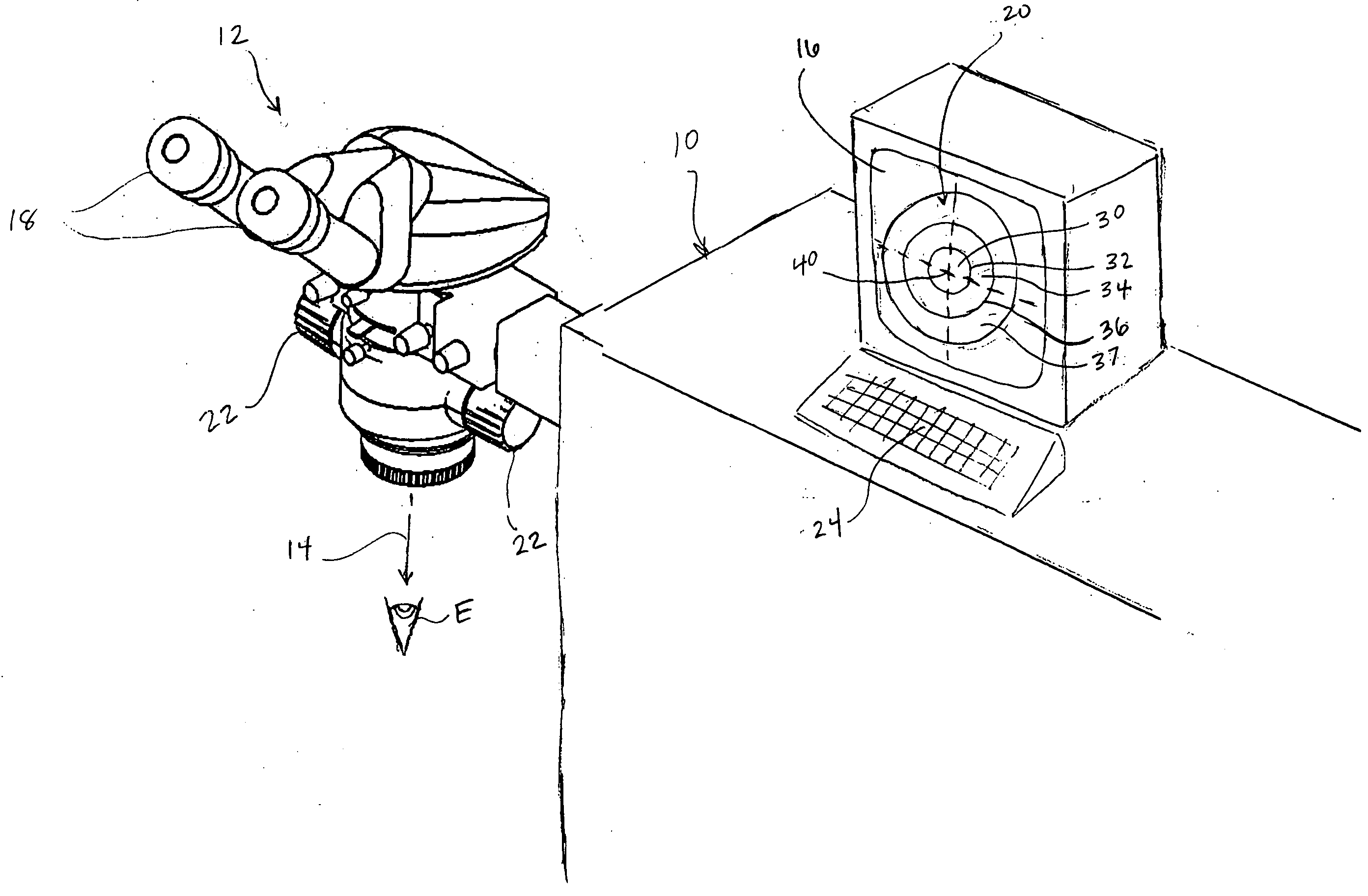
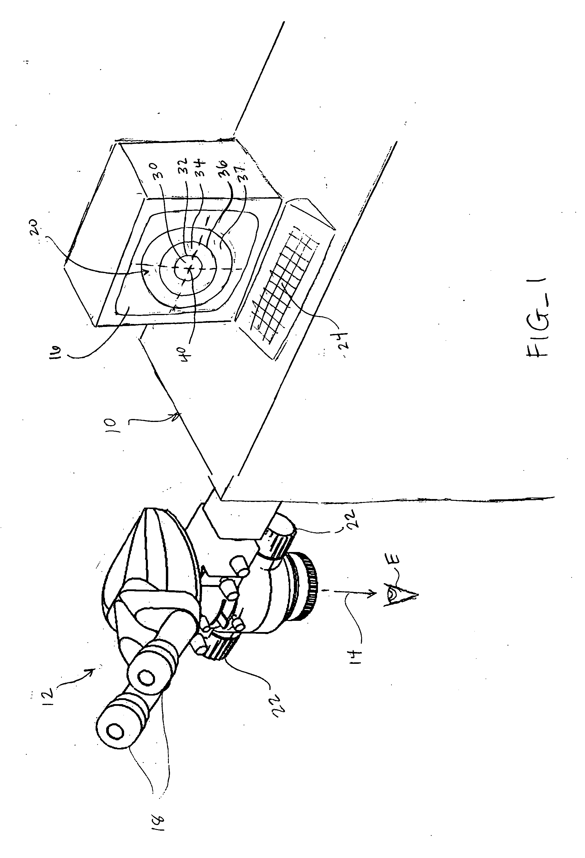
[0033] Referring now to FIG. 1, an embodiment of a laser eye surgery system 10 of the present invention includes a magnification system or microscope 12 through which an eye E of a patient is viewed, typically while the eye E is ablated by a laser beam 14. In preferred embodiments, the microscope 12 comprises a Leica MS5 microscope, however any suitable microscope or microscope components may be used. The eye E may be viewed by a surgeon through eyepieces 18 on the microscope 12. The microscope 12 includes, among other components, knobs 22 for adjusting the magnification of the microscope 12. Thus, by rotation of the knobs 22, the eye E may be viewed under varying levels of magnification through the eyepieces 18. In addition, laser eye surgery system 10 of the present invention includes a monitor display 16 which provides an image 20 of the eye E as viewed through the eye pieces 18. This allows the surgeon and any other assistants or practitioners to easily view the eye E throughout...


PUM


Abstract

Devices, systems and methods for scaling the size and/or position of a marker on a magnified image of an object. In preferred embodiments, the object is an eye that is undergoing laser eye surgery. The eye is viewed through a magnification system or microscope and an image of the eye is presented on a display. One or more markers are present on the image, each identifying a specific target location or landmark on the eye. When a desired magnification setting is selected, the image is scaled accordingly. In addition, one or more of the markers is scaled in size and/or position to reflect the magnification setting. This allows the marker to maintain identification of the target location while reflecting the selected magnification level.

Description

CROSS-REFERENCES TO RELATED APPLICATIONS [0001] NOT APPLICABLE STATEMENT AS TO RIGHTS TO INVENTIONS MADE UNDER FEDERALLY SPONSORED RESEARCH OR DEVELOPMENT [0002] NOT APPLICABLE REFERENCE TO A “SEQUENCE LISTING,” A TABLE, OR A COMPUTER PROGRAM LISTING APPENDIX SUBMITTED ON A COMPACT DISK [0003] NOT APPLICABLE BACKGROUND OF THE INVENTION [0004] The present invention is generally related to magnification systems, particularly sensing magnification settings for use in a visual display of the magnified image, especially for use in laser eye surgery systems. [0005] Laser eye surgery is performed by a laser after optically aligning the laser with the eye using a magnification system or microscope. While it may be possible to make use of lasers having other wavelengths, known laser eye surgery procedures generally include an ultra-violet or modified frequency infrared laser to remove a microscopic layer of stromal tissue from the eye's cornea to change the cornea's contour for varying purpo...

Claims


Application Information

Patent Timeline
IPC IPC(8): A61B19/00G02B21/00G02B21/36
CPCA61B19/5223A61F9/00804G02B21/365G02B21/0012A61B90/20
Inventor SPEDIACCI, CARYHINDI, DAVIDCLOPP, MATHEWFISH, BILL
Owner AMO MFG USA INC
Why Eureka
Try Eureka