Protective relay for power systems having fault distance measurement filter logic

a protection relay and power system technology, applied in the direction of emergency protection circuit arrangement, circuit arrangement, electrical equipment, etc., can solve the problems of inaccurate trip decision and m value variation over time, and achieve the effect of improving the performance of a distance-type protection relay

Active Publication Date: 2005-05-05
SCHWEITZER ENGINEERING LABORATORIES
View PDF2 Cites 7 Cited by
  • Summary
  • Abstract
  • Description
  • Claims
  • Application Information

AI Technical Summary

Benefits of technology

[0006] Accordingly, the present invention is a system for improving the performance of a distance-type protective relay for power systems, wherein the relay includes a calculation circuit responsive to voltage and current values from the power line to produce a quantity (m quantity herein) which is analogous to the distance between the relay and a fault on the power line, wherein the quantity is applied to a distance element for comparison of said quantity with a setting reach value for a selected zone of protection, wherein the system comprises: a filter circuit responsive to said quantity for filtering said quantity before the quantity is applied to the distance element, resulting in the smoothing of the quantity; and a control circuit for controlling the application of the filtered quantity to the distance element such that the filtered quantity is applied only when said quantity is above a preselected first threshold value.

Problems solved by technology

However, faults on the power line which produce an m value greater than the set reach value are beyond the reach of the selected zone of protection, indicating that the relay should not trip the circuit breaker associated with that zone of protection.
However, when a particular fault results in an m value that is just slightly greater than the set reach value, an inaccurate trip decision may be made.
Measurement noise and variations in the voltage and current values from the power line can result in the m value varying over time.

Method used


Image

  • Protective relay for power systems having fault distance measurement filter logic
  • Protective relay for power systems having fault distance measurement filter logic
  • Protective relay for power systems having fault distance measurement filter logic

Examples


Embodiment Construction

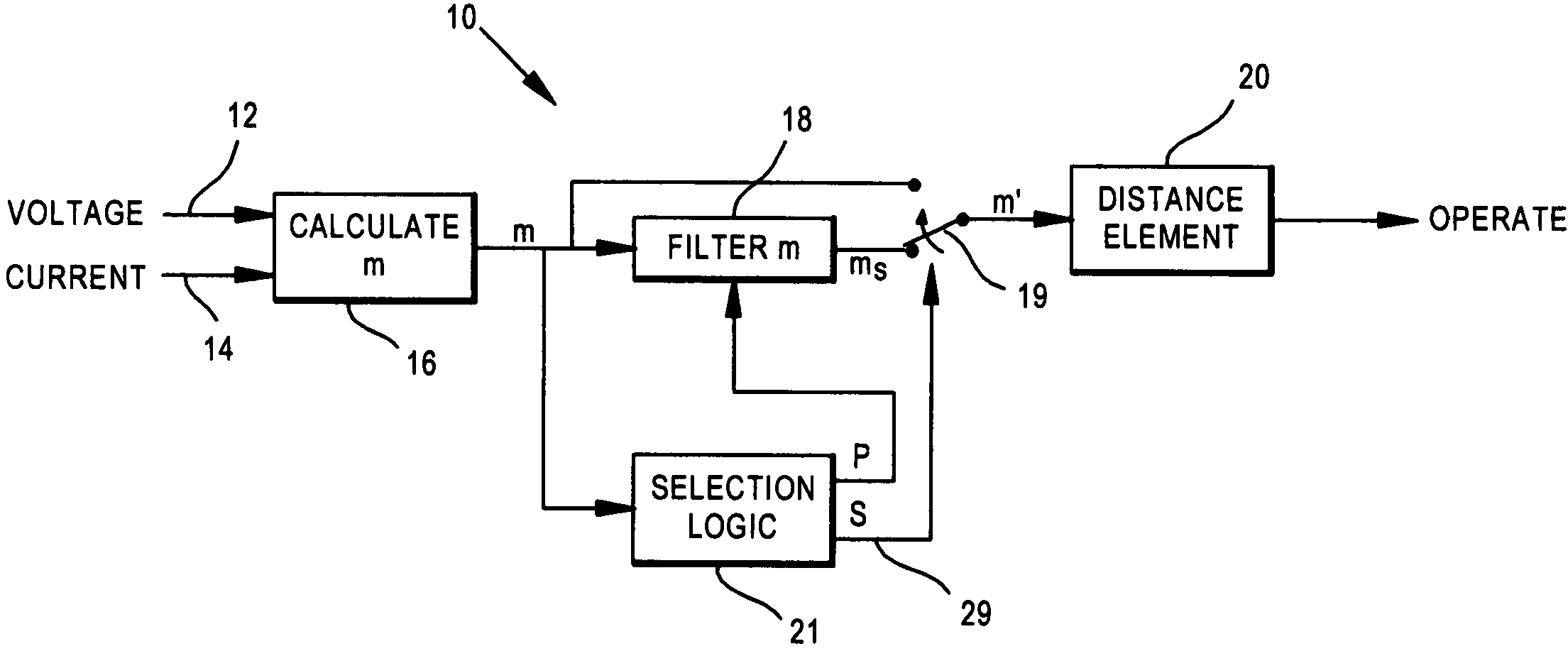
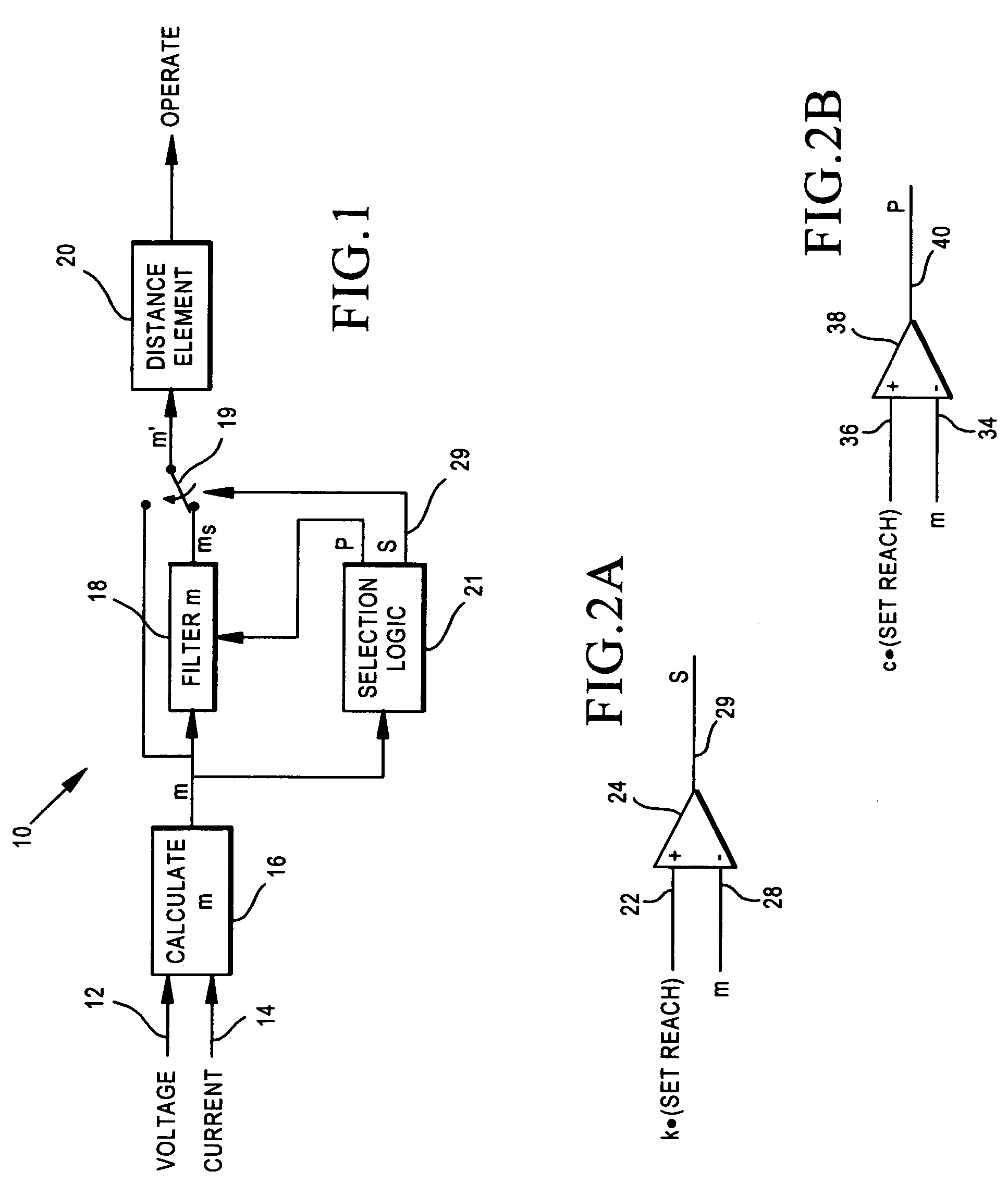
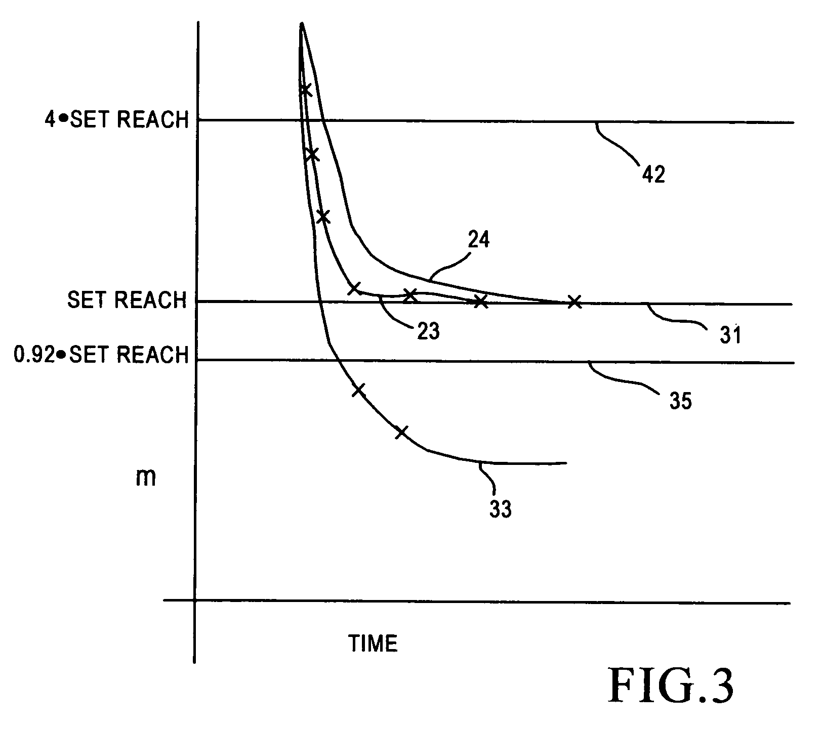
[0011] The present invention is directed toward a distance protective relay for power lines, which determines a quantity, referred to herein as an m value, which is analogous / related to the distance from the relay to a fault on the power line and then compares that m value to a zone one setting value, also referred to herein as a set reach value, to determine whether or not the fault is within the particular zone protection, e.g. zone one protection, associated with setting value. If the fault is within the zone one protection, then the relay will trip the circuit breaker associated with the power line, while if the fault is determined to be outside of the zone one distance, then the relay will not operate, i.e. it will not trip the circuit breaker.

[0012] Occasionally, as discussed above, the m value will be quite close to the setting value associated with zone one protection, i.e. the fault is quite close to the end (the far reach) of the zone. With measurement noise and some vari...


PUM


Abstract

The system is used in a distance-type protective relay which includes a calculation circuit responsive to voltage and current values from a power line to produce a quantity which is analogous to the distance between the relay and a fault on the line, referred to as an m quantity. This quantity is then applied to a distance element/circuit for comparison of said quantity with a setting reach value for a zone one distance protection to determine whether the fault is within zone one protection. The system includes a filter circuit which filters the quantity before it reaches the distance element, resulting in a smoothing of said quantity and rejection of noise therefrom. The system further includes a control circuit which determines whether the filter is to be used in the system in a particular situation, depending upon whether when the value of the quantity is above a selected percentage of the setting reach value.

Description

TECHNICAL FIELD [0001] This invention relates generally to power system protective relays and more particularly concerns a distance-type protective relay which determines whether or not an existing fault is within a particular zone of protection for the relay, for example, within a zone one distance from the relay. BACKGROUND OF THE INVENTION [0002] Distance relays determine, typically by impedance analysis and comparison, whether a particular fault on the power line is within a particular zone (reach) of protection for the relay, for instance a zone one reach. The distance relay calculates an impedance value and then compares that value against a preselected setting value, also referred to as a set reach value, for the zone one distance. If the calculated value is less than the set reach value for zone one, the fault is recognized to be within zone one. A signal is then produced which trips the circuit breaker for that portion of the power line. If the calculated value is greater t...

Claims


Application Information

Patent Timeline
Patent Type & Authority Applications(United States)
IPC IPC(8): H02H3/40
CPCH02H3/40
Inventor SCHWEITZER, EDMUND O. IIIMOONEY, JOSEPH B.
Owner SCHWEITZER ENGINEERING LABORATORIES
Why Eureka
Try Eureka