
Material testing method

a testing method and material technology, applied in the direction of force measurement, acceleration measurement using interia forces, instruments, etc., can solve the problems of inability to accurately measure dynamic force, inability to guarantee measurement accuracy, and delay in the response the change in the shape of the output of the sensor

Inactive Publication Date: 2005-05-12
GUNMA UNIVERSITY
View PDF8 Cites 9 Cited by
  • Summary
  • Abstract
  • Description
  • Claims
  • Application Information

AI Technical Summary

Benefits of technology

[0006] In view of the above point, it is an object of the present invention to provide a material testing method, which can ensure the accuracy of measurement of a force acting on an object to be measured so that the mechanical properties of the object to be measured can be accurately evaluated.
[0008] Upon vibration of the mass-spring system, the force exerted from the weight to the object to be measured and the force exerted from the object to be measured to the weight are equal in magnitude but opposite in direction according to the action-reaction law. Under the conditions in which the frictional force acting on the weight is negligible, the inertial force of the weight becomes equal to the force exerted from the object to be measured to the weight. For this reason, the force acting on the object to be measured can be measured with high precision from the inertial force of the weight. Further, since the weight is displaced according to the strain on the object to be measured, the amount of strain on the object to be measured can be determined with high precision from the displacement of the weight. Thus the mechanical properties of the object to be measured can be accurately evaluated based on the inertial force and displacement of the weight. Particularly, according to the present invention, the accuracy of evaluation of mechanical properties of an object to be measured under varying loads is improved dramatically compared to the conventional case using the force sensor.
[0009] The inertial force of the weight is equal to the product of the mass and acceleration of the weight. If a light wave interferometer, which launches measurement light at a reflecting part provided on the weight and measures the state of the reflected light from the reflecting part, is used, the displacement, velocity, and acceleration of the weight can be determined from the state of the reflected light, thereby calculating the inertial force of the weight accurately from the determined acceleration of the weight. In this case, since the inertial force and displacement of the weight can be measured by the light wave interferometer alone, it is cost efficient. And since the inertial force and displacement of the weight can be measured by the light wave interferometer alone, the synchronization of the measured values of the displacement, velocity, acceleration and inertial force of the weight are automatically guaranteed.
[0010] It is also desired that the weight be supported by a linear bearing to limit the motion of the weight to one degree of freedom. Particularly, if the weight is supported by a pneumatic linear bearing, the frictional force acting on the weight can be reduced to a minimum, so that the difference between the inertial force of the weight and the force acting on the object to be measured can be reduced as much as possible, thereby the accuracy of measurement is improved.

Problems solved by technology

However, when a dynamic force is exerted on the force sensor, unique phenomena occur, such as a delay in the response of the output of the sensor and the change in the shape of the output of the sensor.
In this case, even when the detection output of the force sensor system is calibrated by the static calibration method, the dynamic force cannot be measured accurately.
Thus, when a force acting on an object to be measured changes, the accuracy of measurement cannot be guaranteed even if the force is measured with the force sensor, and this makes it difficult to evaluate the mechanical properties of the object to be measured accurately.
Furthermore, it is usually difficult to synchronize the measurement of force using a force sensor and measurement of strain using a displacement sensor, because both the force sensor and the displacement sensor have some delay in their output and the deformation of the shape of output signal.

Method used


Image

  • Material testing method
  • Material testing method
  • Material testing method

Examples


first embodiment

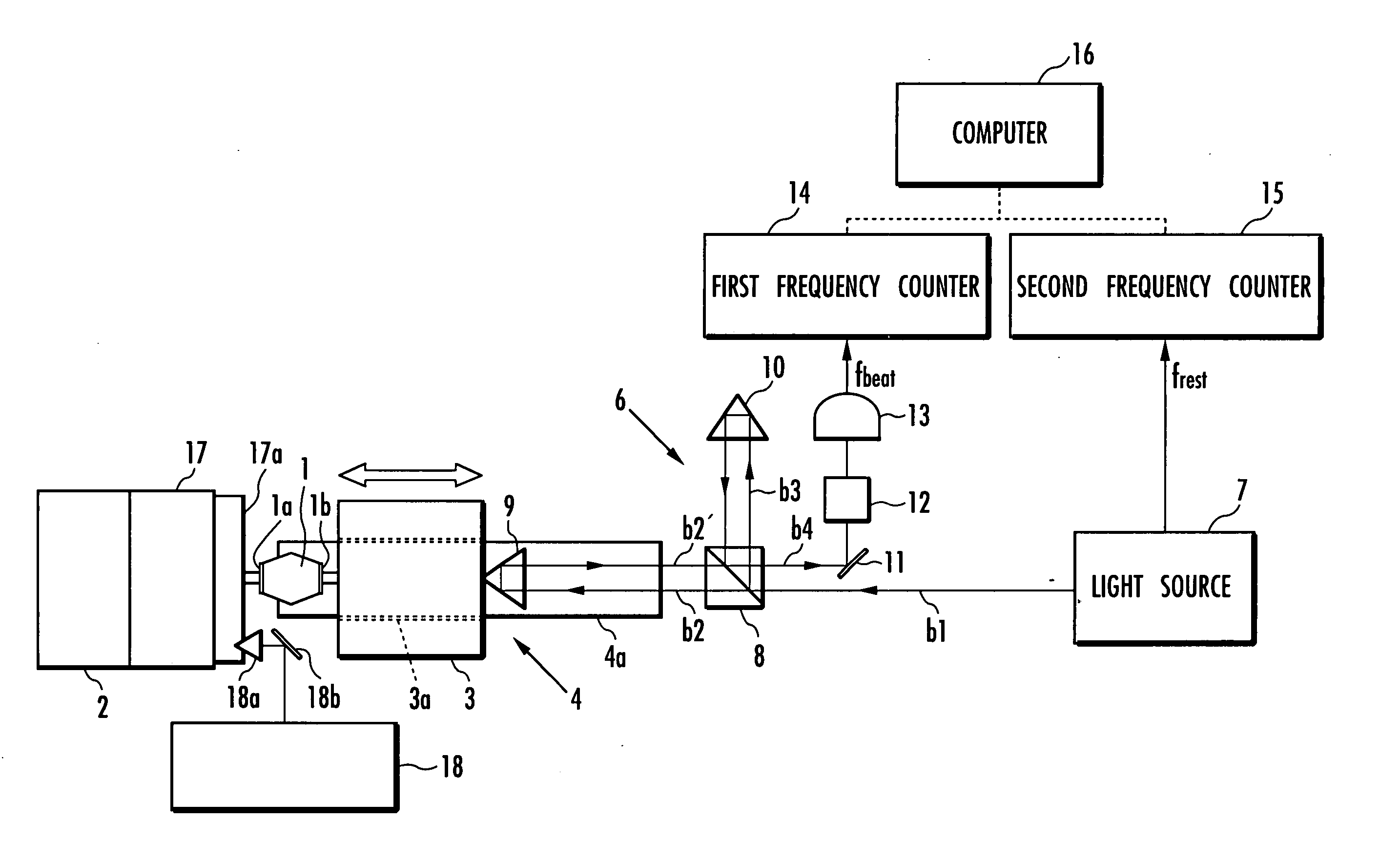
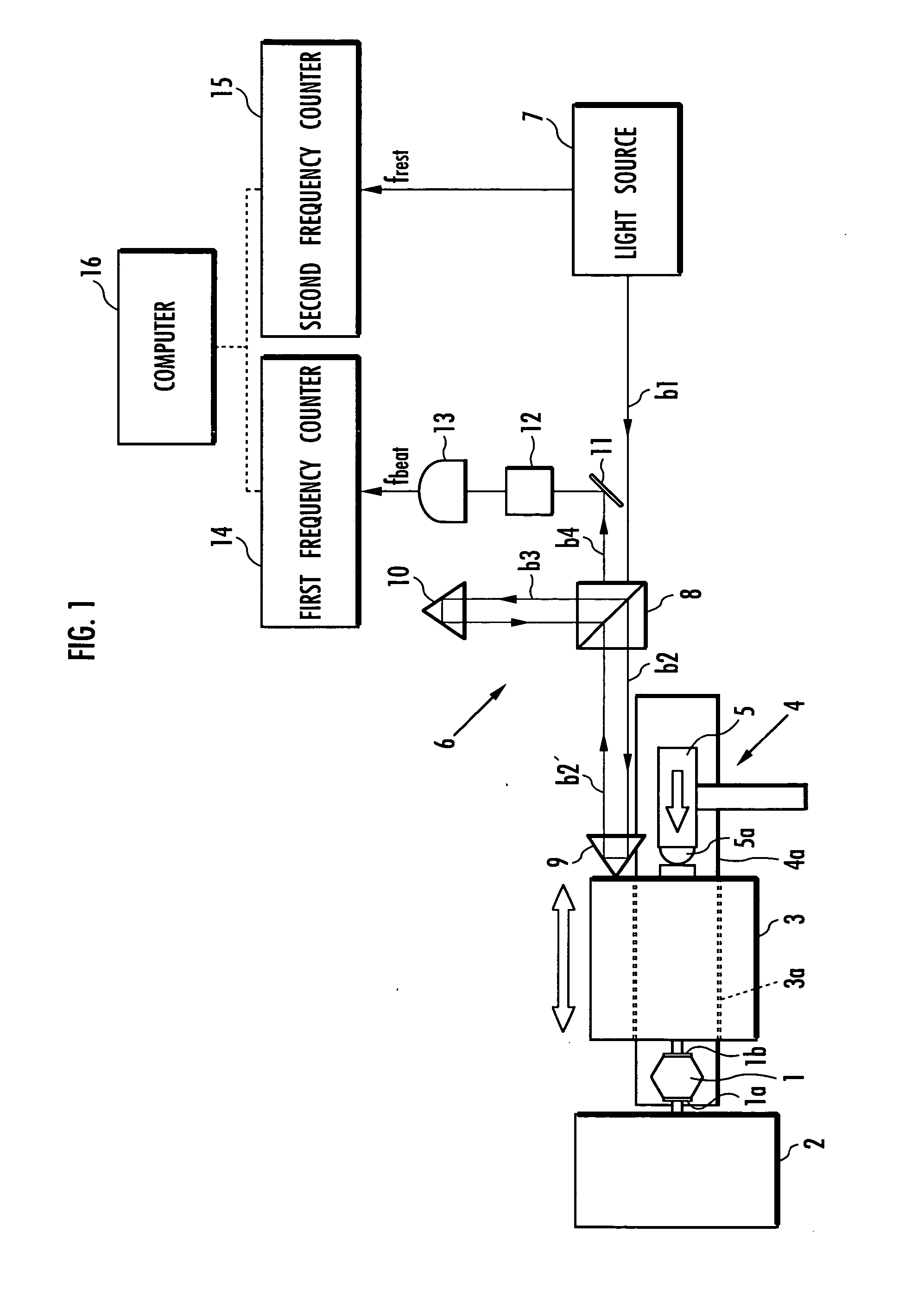
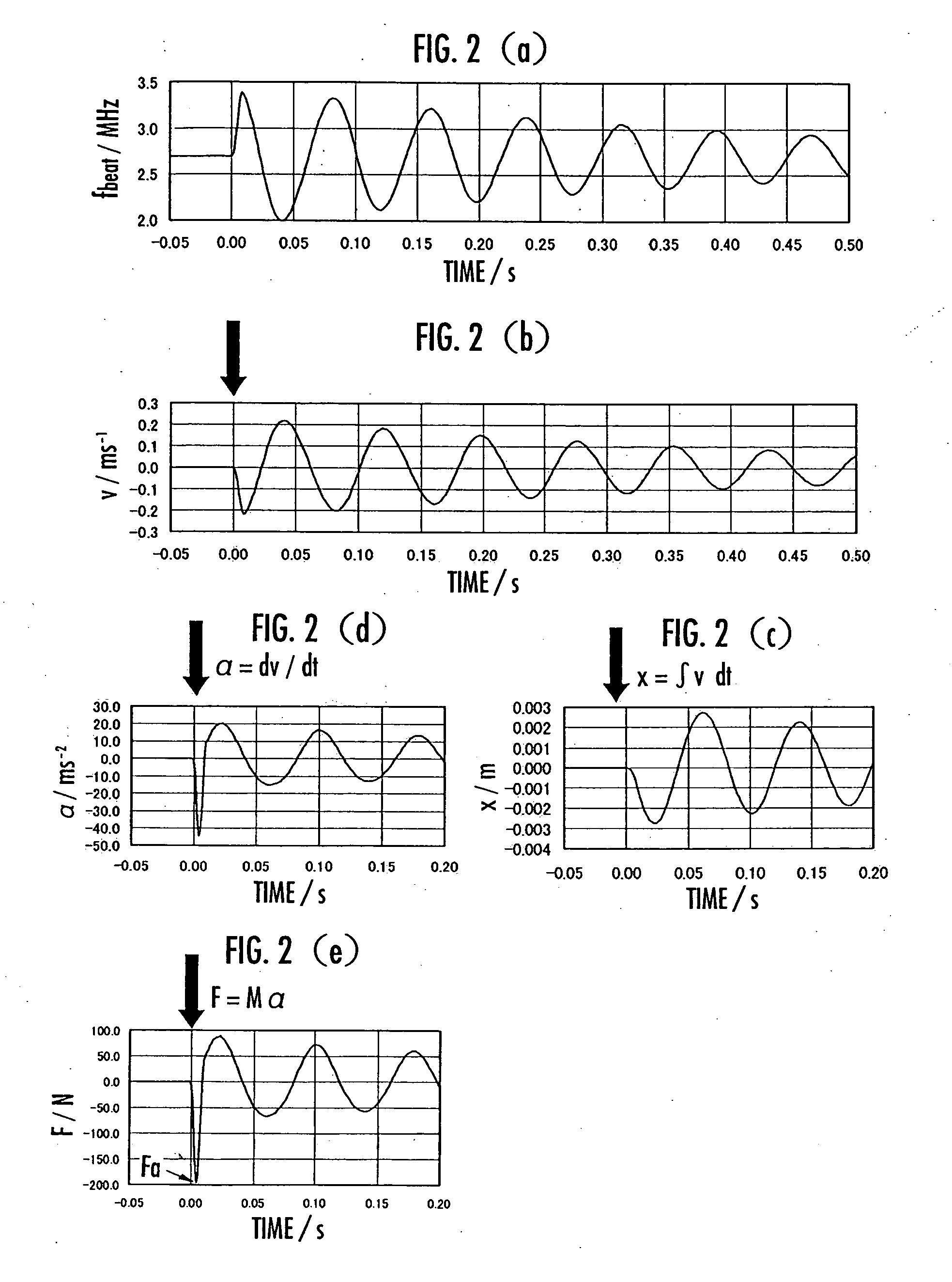
[0022] In the first embodiment, an impulsive force is applied by a hammer 5 to the weight 3 to apply vibration to the mass-spring system. The hammer 5 has a rubber pad 5a at its tip. Upon the application of vibration, the force exerted from the weight 3 to the object to be measured 1 and the force exerted from the object to be measured 1 to the weight 3 are equal in magnitude but opposite in direction according to the action-reaction law. Further, since the weight 3 is supported by the pneumatic linear bearing 4 and therefore the frictional force acting on the weight 3 is negligible, the inertial force F of the weight 3 becomes equal to the force exerted from the object to be measured 1 to the weight 3. In other words, it can be considered that the inertial force F of the weight 3 is a parameter that accurately represents the force acting on the object to be measured 1. It can also be considered that the displacement x of the weight 3 is a parameter that accurately represents the st...

second embodiment

[0032] For material tests using the testing apparatus according to the first or second embodiment, various types of measurement equipment that cover the whole field of view can be provided in order to check the internal distribution of acceleration, velocity, and displacement of the object to be measured 1. The material testing method can also be combined with a numerical analysis method such as a finite element method. It enables a more sophisticated evaluation of mechanical properties of materials. Further, the use of a small weight, such as a weight of about 1 g, as the weight 3 makes it possible to carry out material tests on small forces, such as forces of about 1 μN or less. In this case, it is possible to test the mechanical properties of various materials used in a micromachine or nanomachine and the like.

[0033] Further, in the testing apparatuses according to the first and second embodiments, the direction of the motion of the weight 3 is horizontal, but the linear bearing ...


PUM


Abstract

The present invention aims to achieve accurate measurement and evaluation of mechanical properties of an object to be measured 1 without use of a force sensor. A weight 3 is attached to the object to be measured 1 to form a mass-spring system in which the object to be measured 1 serves as a spring element. Then vibration is applied to the mass-spring system to measure the inertial force acting on the weight 3 and the displacement of the weight 3 so that the mechanical properties of the object to be measured 1 will be evaluated based on the inertial force and displacement. A light wave interferometer 6 measures the displacement velocity of the weight 3 to calculate the inertial force from the acceleration determined by differentiating measured values of the displacement velocity of the weight 3 and calculate the displacement of the weight 3 by integrating the measured values of the displacement velocity of the weight 3.

Description

BACKGROUND OF THE INVENTION [0001] 1. Field of the Invention [0002] The present invention relates to a material testing method for evaluating mechanical properties of objects to be measured. [0003] 2. Description of Related Art [0004] This type of material testing method is designed to determine the magnitude of a force acting on an object to be measured and the amount of strain on the object to be measured so as to evaluate mechanical properties such as an elastic coefficient of the object to be measured based on the measured force and strain. In the conventional method, the force acting on the object to be measured is measured with a force sensor such as a load cell (for example, see JSME Mechanical Engineers' Handbook, B3, p 74, published by The Japan Society of Mechanical Engineers (JSME) on Apr. 15, 1987). [0005] A calibration technique (static calibration method) for the detection output of a force sensor system for detecting static forces is already established. However, when...

Claims


Application Information

Patent Timeline
IPC IPC(8): G01P15/03G01B7/16G01B11/16G01L1/00G01N3/00G01N3/06G01N3/28G01N3/34G01P15/16
CPCG01B11/161G01N3/34G01N3/06
Inventor FUJII, YUSAKUYAMAGUCHI, TAKAO
Owner GUNMA UNIVERSITY
Learn More