Universal slide assembly for molding and casting systems

a technology of injection molding and casting system, applied in the direction of combs, manufacturing tools, buttons, etc., can solve the problems of troublesome, expensive and time-consuming individualization of slides, holes in molding or casting, etc., and achieve the effect of convenient operation, cost-effectiveness, and convenient installation

a technology of injection molding and casting system, applied in the direction of combs, manufacturing tools, buttons, etc., can solve the problems of troublesome, expensive and time-consuming individualization of slides, holes in molding or casting, etc., and achieve the effect of convenient operation, cost-effectiveness, and convenient installation

US20050098295A1Inactive Publication Date: 2005-05-12DUBAY RICHARD L

Image

  • Universal slide assembly for molding and casting systems
  • Universal slide assembly for molding and casting systems
  • Universal slide assembly for molding and casting systems

Examples


Embodiment Construction

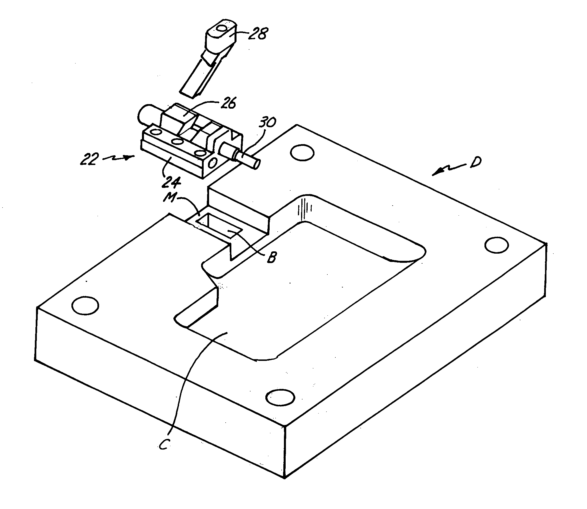
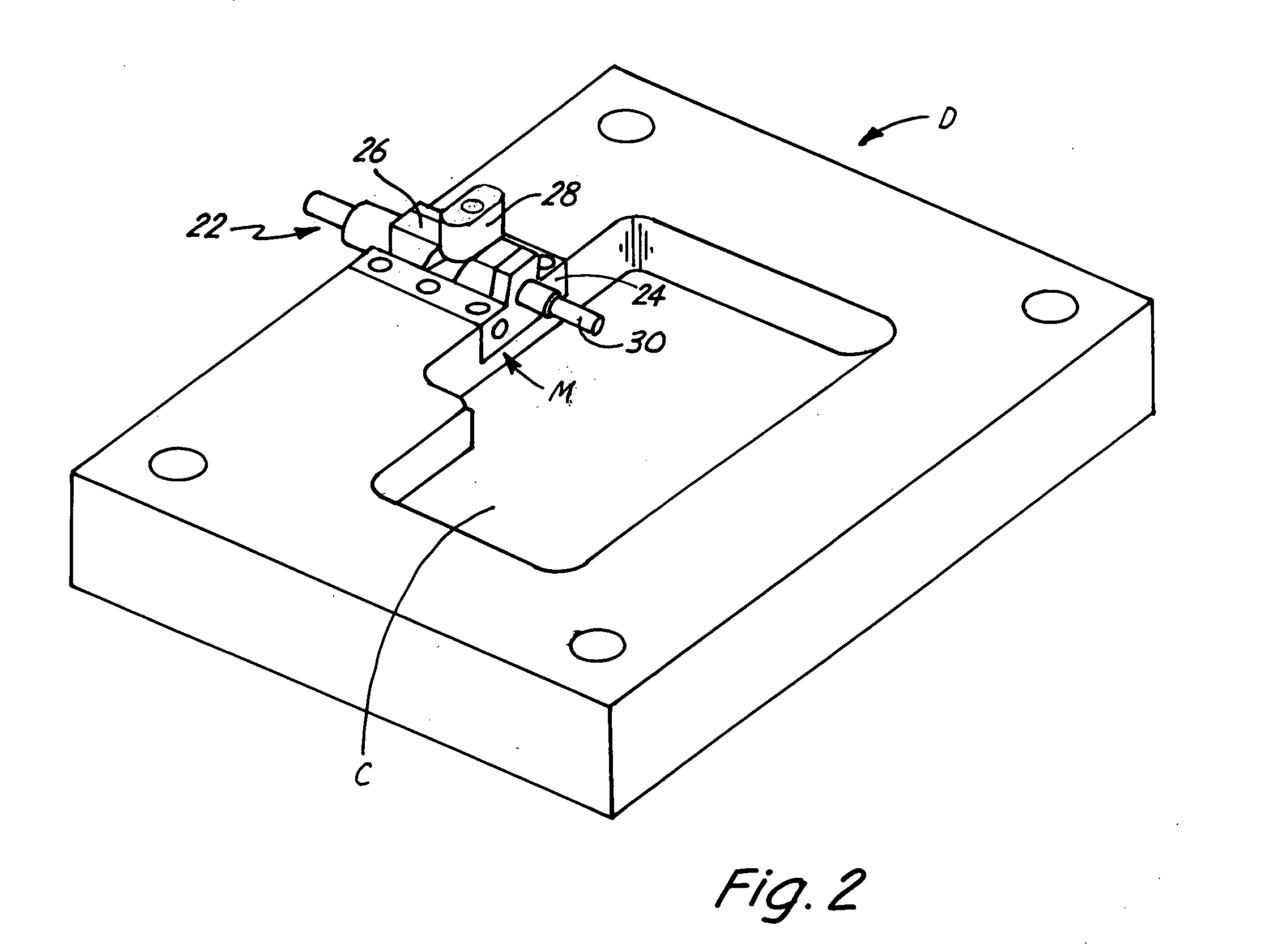
[0043]FIGS. 1 and 2 are perspective views of universal slide assembly 22 and die block D, illustrating the ease of use and installation of universal slide assembly 22. FIG. 1 is an exploded view that illustrates universal slide assembly 22 positioned above die block D. FIG. 2 illustrates universal slide assembly 22 mounted to die block D for use with injection molding or die casting processes. Universal slide assembly 22 is a universal design that includes base 24, slide 26, cam lever 28, and pin 30. Die block D in FIGS. 1 and 2 is a movable-die half and includes mounting slot M and core C. Mounting slot M includes block slot B. Core C is a portion of the core or cavity in die block D where plastic or molten metal is injected for curing or solidification.

[0044] In addition to the components illustrated, FIGS. 1 and 2 also incorporate a fixed-die half (not shown), to which die block D is clamped, enclosing core C to create the complete molding or casting core. Alternatively, die blo...


PUM

PropertyMeasurementUnit
angleaaaaaaaaaa
angleaaaaaaaaaa
angleaaaaaaaaaa

Abstract

The present invention is a universal slide assembly for molding or casting systems used to introduce complex designs to moldings and castings, which is cost effective, easy to install, and easy to operate, and includes a base, a slide, and a cam lever. The base is directly insertable into a movable-die half for immediate use without requiring the slide to be individually designed or adapted to a particular movable-die half. The cam lever is capable of moving the slide towards and away from a core without the use of hydraulic power, through cam action.

Description

CROSS-REFERENCE TO RELATED APPLICATION(S) [0001] Priority is claimed under U.S. Provisional Application No. 60 / 413,992, entitled Universal Slide Assembly for Molding and Casting Systems, and filed Sep. 26, 2002, which is incorporated by reference.BACKGROUND OF THE INVENTION [0002] The present invention relates to injection molding and die casting processes. In particular, the present invention relates to injection molding and die casting slide systems. [0003] Injection molding and die casting are manufacturing processes for producing a multitude of shapes and designs for plastic and metal products. Such processes generally incorporate two-component systems. The two components are the fixed-die half and the movable-die half. The fixed-die half is secured to the apparatus and contains a portion of a core or core where plastic or molten metal is injected into for curing or solidification. [0004] In contrast, the movable-die half is capable of moving, and contains the other portion of t...

Claims


Application Information

Patent Timeline
12 May 2005
Publication
US20050098295A1
IPC
B22D17/08; B22D17/24; B22D17/26; B22D33/04; B29C; B29C45/33
CPC
B22D17/24; B29C45/332; B22D17/26
Inventors
DUBAY, RICHARD L.