Recuperator assembly and procedures

a gas turbine engine and assembly technology, applied in the direction of machines/engines, lighting and heating apparatus, laminated elements, etc., can solve the problem of visible indication of improper assembly, and achieve the effect of increasing physical size and increasing heat transfer demands

Active Publication Date: 2005-05-12
CAPSTONE TURBINE
View PDF65 Cites 17 Cited by
  • Summary
  • Abstract
  • Description
  • Claims
  • Application Information

AI Technical Summary

Benefits of technology

[0014] The much larger physical size and much greater heat transfer demands required for a recuperator suitable for use with a 200 kW microturbine led the assignee of the present invention to develop a completely new design for an annular counter-flow primary surface recuperator.
[0015] The physical dimensions of the microturbine, combined with the surface area required to provide the necessary heat transfer, led to the construction of an annular recuperator having a relatively high ratio of radial width to axial length, which in turn led to the design of an internal recuperator core segment geometry which substantially improves compressed air flow to the radially outer portions of each recuperator core segment.
[0016] Additionally, new manufacturing techniques provide a recuperator core segment construction having a minimum number of parts and providing for efficient and economical assembly thereof
[0021] Accordingly, it is an object of the present invention to provide an improved recuperator core segment construction.
[0023] And another object of the present invention is the provision of a recuperator core segment and a method of assembly thereof which insures proper assembly of the recuperator core segment from one first heat exchanger foil and one second heat exchanger foil, wherein the first and second heat exchanger foils have different fin fold patterns to prevent nesting of the fin folds of adjacent heat exchanger foils.
[0024] And another object of the present invention is the provision of a recuperator core segment construction and assembly method wherein each recuperator core segment is provided with an offset indexing lip along its radially inner edge so as to insure proper orientation of one recuperator core segment relative to another and to prevent nesting of fin folds between adjacent recuperator core segments.

Problems solved by technology

When an improper assembly is made of two first heat exchanger foils or two second heat exchanger foils, a misalignment of corners results thereby visibly indicating an improper assembly.

Method used


Image

  • Recuperator assembly and procedures
  • Recuperator assembly and procedures
  • Recuperator assembly and procedures

Examples


Embodiment Construction

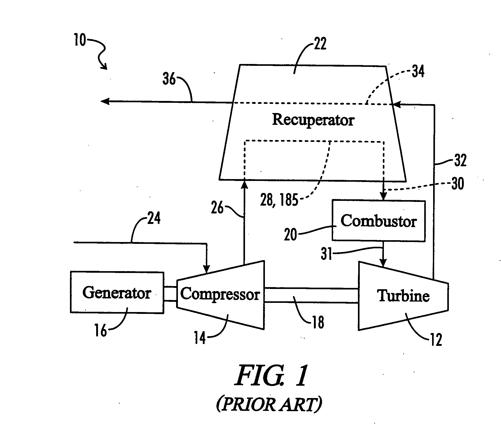
[0054] Referring now to the drawings, and in particular to FIG. 1, a microturbine is shown and generally designated by the numeral 10. The microturbine 10 and its major components are schematically illustrated in FIG. 1. The microturbine includes a turbine 12, a compressor 14 and a generator 16 all of which are located upon a common shaft 18. The microturbine further includes a combustor 20 and a recuperator 22 which is the particular object of the present invention.

[0055] Fresh combustion air enters the microturbine 10 as indicated at the microturbine inlet air passage 24. The combustion air typically passes through the generator 16 to provide some cooling to the components of the generator 16. The inlet air is then compressed by compressor 14 and high pressure air exits compressor 14 via the recuperator compressed air passage 26 which directs the compressed air through the recuperator 22 along C-shaped path 28. The compressed air is preheated in the recuperator 22, and the prehea...


PUM

PropertyMeasurementUnit
rated poweraaaaaaaaaa
thicknessaaaaaaaaaa

Abstract

A construction of recuperator core segments is provided which insures proper assembly of the components of the recuperator core segment, and of a plurality of recuperator core segments. Each recuperator core segment must be constructed so as to prevent nesting of fin folds of the adjacent heat exchanger foils of the recuperator core segment. A plurality of recuperator core segments must be assembled together so as to prevent nesting of adjacent fin folds of adjacent recuperator core segments.

Description

[0001] This application is a Non-Provisional Utility application which claims benefit of co-pending U.S. Provisional Patent Application Ser. No. 60 / 515,080 filed Oct. 28, 2003, entitled “Recuperator Construction for a Gas Turbine Engine”, and U.S. Provisional Patent Application Ser. No. 60 / 559,270, filed Apr. 2, 2004, entitled “Recuperator Construction for a Gas Turbine Engine”, both of which are hereby incorporated by reference.[0002] This invention was made in conjunction with the US Department of Energy's Advanced Microturbine System Project under contract number DE-FC02-00CH11058. The United States government may have certain rights in this invention.BACKGROUND OF THE INVENTION [0003] 1. Field of the Invention [0004] The present invention relates generally to recuperators for gas turbine engines. More particularly, the present invention relates to component construction and assembly procedures designed to provide for foolproof assembly of the recuperator core. [0005] 2. Descript...

Claims


Application Information

Patent Timeline
Patent Type & Authority Applications(United States)
IPC IPC(8): F28D9/00F28F3/00F28F3/02
CPCF05B2220/302F28D9/0018F28D9/0068Y10T29/49366F28F3/025Y10S165/906F28D21/001
Inventor KANG, YUNGMOMCKEIRNAN, ROBERT D. JR.
Owner CAPSTONE TURBINE
Why Eureka
Try Eureka