Adjustable hanger bracket assembly

Inactive Publication Date: 2005-05-12
C & S MFG
View PDF10 Cites 44 Cited by
  • Summary
  • Abstract
  • Description
  • Claims
  • Application Information

AI Technical Summary

Benefits of technology

[0010] The clamps are integrally formed with a supporting base portion with an oppositely extending clamping arms. One set of bifurcated clamping arms is formed to provide inwardly facing surfaces, preferably dimensioned to embrace the outer, exposed surface of the span member. The base portion of each clamp further encloses oppositely extending, bifurcated clamping arms each cooperating to provide inwardly facing clamping surfaces for resiliently embracing a respective tubing or piping member. Each of the integrally formed, bifurcated arms are provided with retaining portions permitting “snap action” during entry and retention of a respective pipe or tubing. Each clamp is further designed to provide

Problems solved by technology

This often requires tedious manual adjustment of wire twists and wire ties and brackets for securing the tubing to a hanger bracket at a relati

Method used


Image

  • Adjustable hanger bracket assembly
  • Adjustable hanger bracket assembly
  • Adjustable hanger bracket assembly

Examples


Embodiment Construction

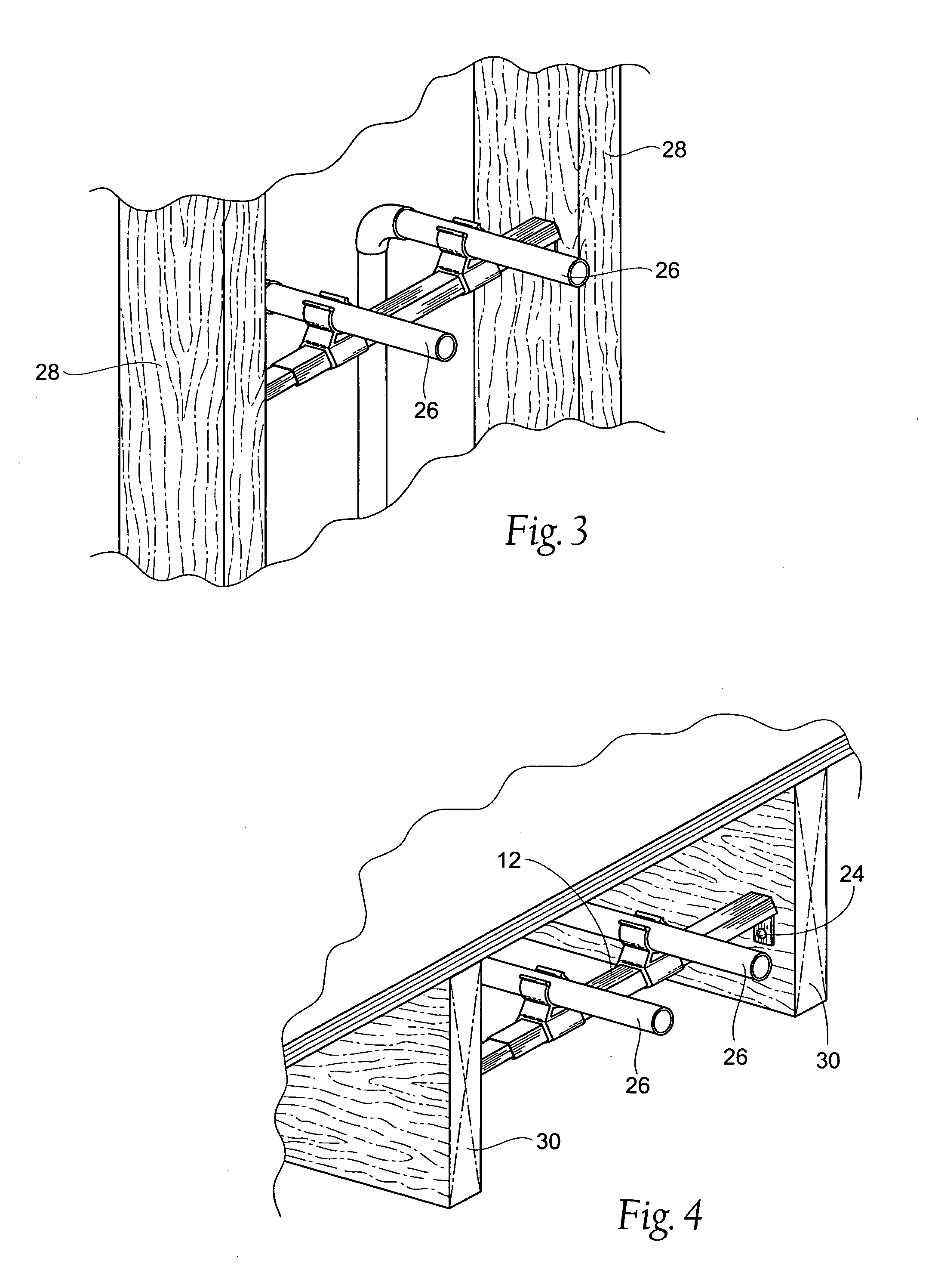
[0015]FIGS. 3 and 4 illustrate the versatility in installation of the novel bracket assembly 10. FIG. 4 is directed to an installation utilized for under-floor radiant heating, whereas FIG. 3 illustrates an installation of a substantially identical assembly utilized for supporting water inlets positioned between a pair of spaced apart, adjacent, wall stud supporting members 28.

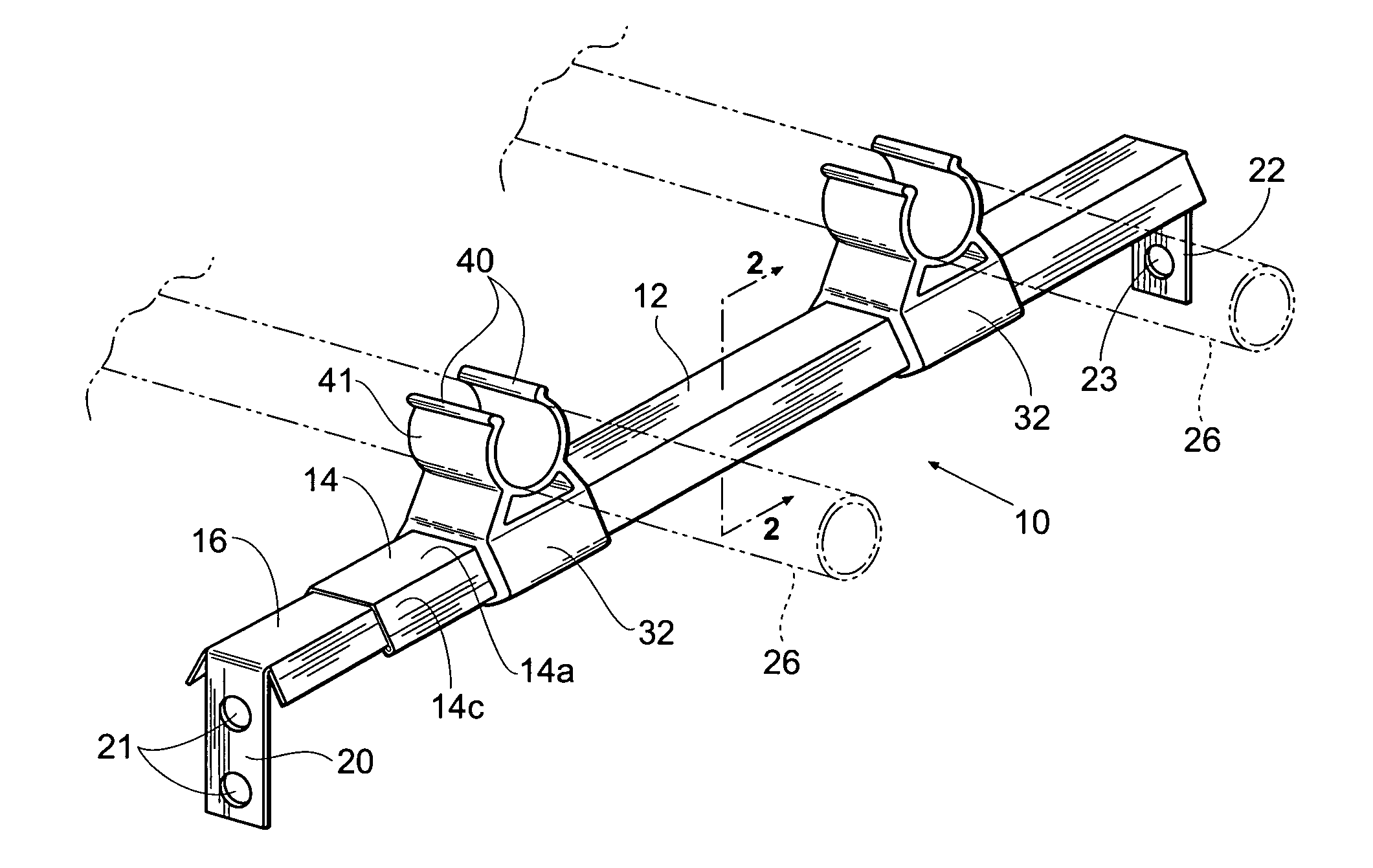
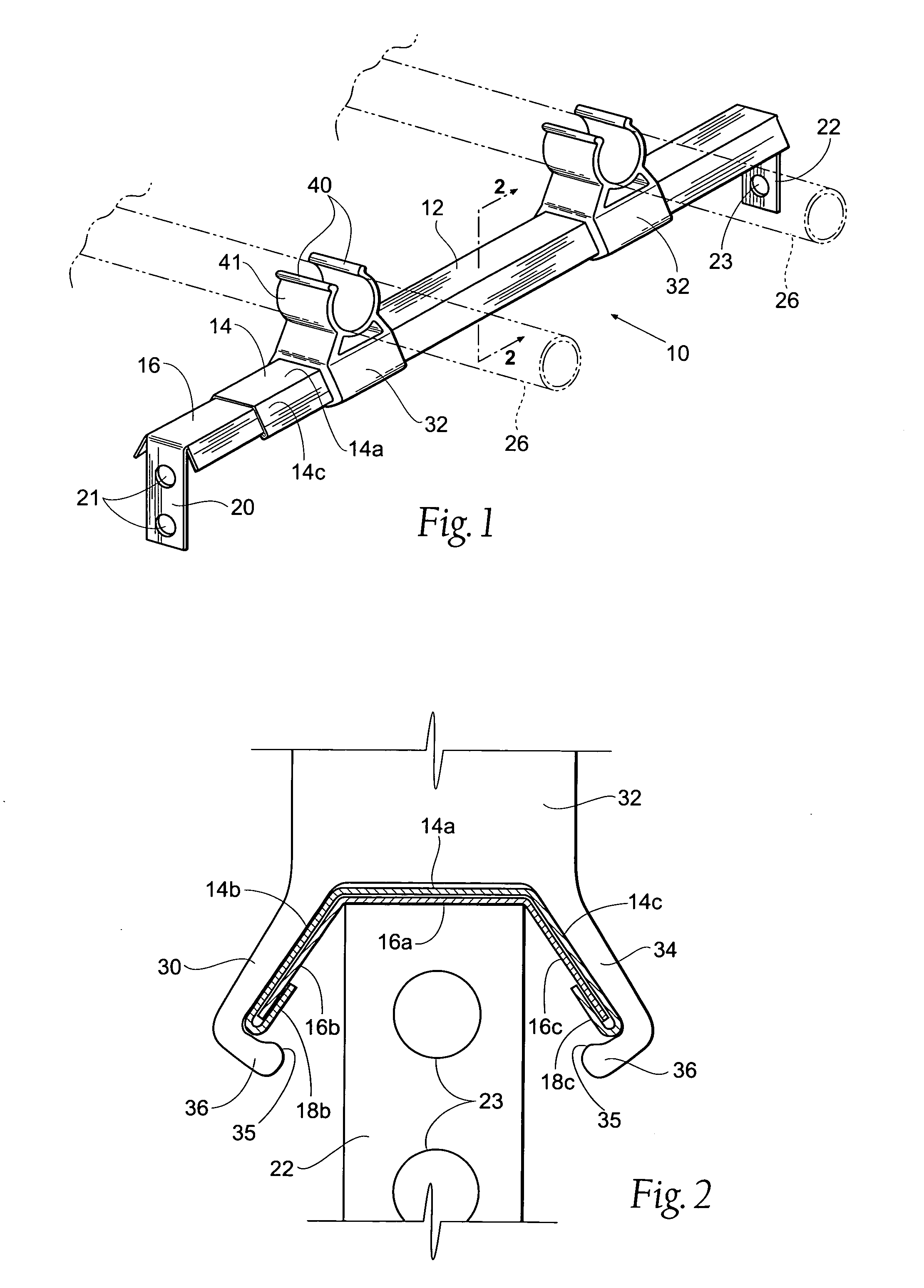
[0016] As will be apparent from the following detailed description, the present assembly may have a multitude of applications, and also may be modified, for instance, to be secured by use of pointed, arrow-like projections (not shown) designed to penetrate into the fibers of wood support members, such as joists or studs. With reference to FIG. 1, it will be observed that the assembly 10 is comprised of a longitudinally extendable span member 12. The span member 12 is comprised of two relatively slidable upper and lower segments 14 and 16, respectively, wherein the uppermost or top segment 14 overlays and is i...


PUM


Abstract

An adjustable hanger bracket and bracket assembly for tubular members. The assembly includes a longitudinally extendable span member arranged to be fastened to facing sides of laterally spaced supporting members, such as horizontally disposed joists or vertically positioned wall studs. Longitudinally adjustable brackets slidably engage the external surface of the slidably adjustable span member to support tubing or piping sections which may be positioned between adjacent studs or joists.

Description

BACKGROUND OF THE INVENTION [0001] 1. Field of the Invention [0002] The present invention relates to a device having special application for supporting flexible PEX (cross-linked polyethylene), or copper tubing, used in radiant heating installations, as well as for stubbing out copper tubing supplying hot and cold water for kitchen and bathroom usage. [0003] 2. Background Information [0004] It is usual to provide supporting brackets for PEX or copper tubing for supplying heated radiant heat applications under floors and within walls of buildings, as well as for stubbing out copper tubing used in hot or cold supply lines while positioned in the area between floor joists of a building, or between wall studs. In the latter case, such tubing is often used for supplying hot and / or cold water from a source to various lavatory, toilet or other fixtures used in commercial lavatories and in home bathrooms and kitchens. It is essential, particularly in radiant heating, to maintain the spatial...

Claims


Application Information

Patent Timeline
IPC IPC(8): F16L3/13F16L3/24
CPCF16L3/24F16L3/13
Inventor COLLINS, JOHN D.
Owner C & S MFG
Why Eureka
Try Eureka