Passive thermal switch

a passive thermal switch and electronic system technology, applied in the direction of cooling/ventilation/heating modification, semiconductor device details, semiconductor/solid-state device details, etc., can solve the problems of high environmental impact, low temperature of electronic components, and many electronic systems implemented in aerospace environments, so as to reduce heat dissipation from the system, control the temperature of electronic system components, and reduce the effect of heat dissipation

Inactive Publication Date: 2005-05-12
HONEYWELL INT INC
View PDF15 Cites 42 Cited by
  • Summary
  • Abstract
  • Description
  • Claims
  • Application Information

AI Technical Summary

Benefits of technology

[0006] The present invention provides a passive thermal switch assembly that simply, easily, and inexpensively controls electronic system component temperatures within normal operating ranges during normal system operations, and that reduces heat dissipation from the system during a cold startup, to thereby enable a relatively rapid component temperature rise.

Problems solved by technology

Many electronic systems, such as those implemented in an aerospace environment, may be subjected to potentially harsh environmental conditions, such as relatively low temperatures.
Thus, when these systems are shutdown, the electronic component temperatures may also be subject to relatively low temperatures, which may fall below normal operating temperature ranges.

Method used


Image

  • Passive thermal switch
  • Passive thermal switch
  • Passive thermal switch

Examples


embodiment 600

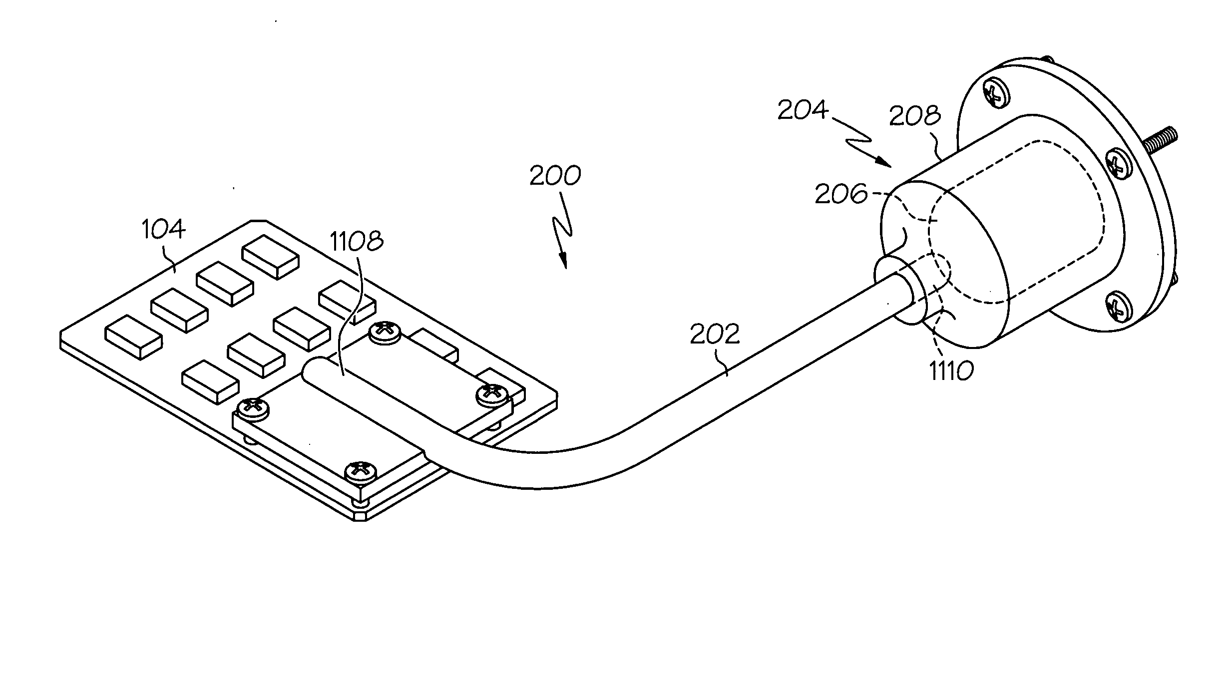
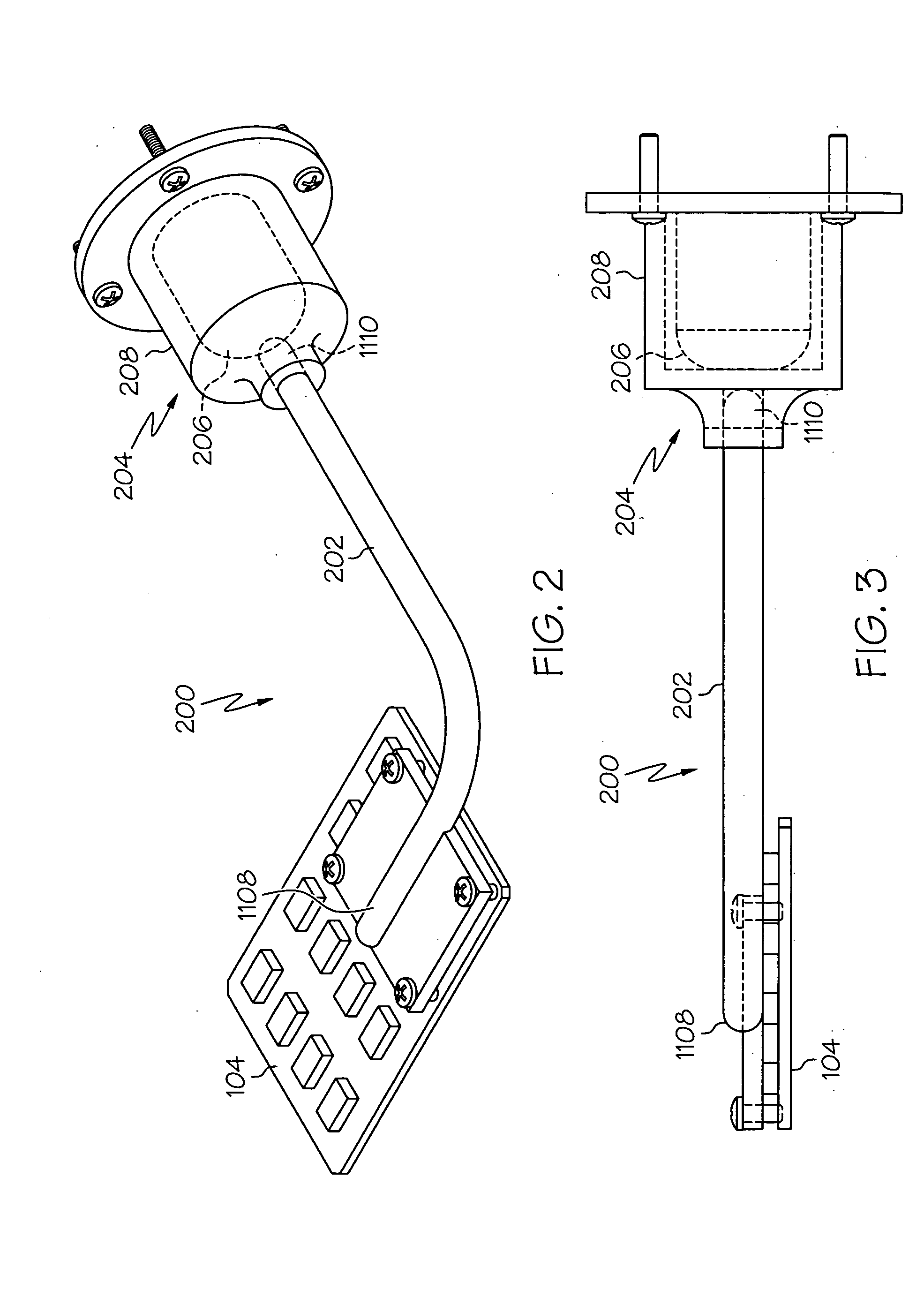
[0032] Yet another passive thermal switch embodiment 600 is shown in FIGS. 6 and 7, in which like reference numerals refer to like parts of the previous embodiments, and will now be described. This passive thermal switch 400 is similar to the previously described embodiments, in that the switch 204 has first 206 and second 208 contacts, the heat pipe evaporator end 1108 is coupled to one or more of the circuit components 104, and the heat pipe condenser end 1110 is coupled to the switch first contact 206. However, as will now be described, the configuration of the first 206 and second 208 switch contacts is significantly different than the two previous embodiments.

[0033] In the switch 204 of this third embodiment, the first 206 and second 208 contacts are disposed adjacent one another. However, neither switch contact 206, 208 at least partially surrounds the other switch contact 208, 206. Instead, the first 206 and second 208 contacts are each preferably configured as a plate. The f...

third embodiment

[0034] With the passive thermal switch 600 of FIGS. 6 and 7, when the circuit components 104 are at or below a predetermined temperature, such as during a cold startup, the switch 204 is configured such that the first 206 and second 208 switch contacts are thermally decoupled from one another. As such, the heat pipe 202 is thermally decoupled from the heat sink, and the circuit components 104 will begin heating up. As the circuit components 104 heat up, heat is transferred to the heat pipe 202, and from the heat pipe 202 to the first contact 206 and the tendon 602. This, in turn, causes the tendon 602 to heat up and begin changing its shape in a manner that the tendon 602 begins contracting, and moving the first contact 206 toward the second contact 208. When the circuit components 104 reach the normal operating range, the tendon 602 preferably reaches a temperature at which its shape is changed sufficiently to cause it to move the first contact 206 into engagement with, and thereby...

fourth embodiment

[0036] The switch 204 in this fourth embodiment additionally includes an expansion column 802 that is coupled between the first contact 206 and another structure such as, for example, the chassis 102. The expansion column 802 is preferably constructed, at least in part, of a shape memory metal or metal alloy. As with the other embodiment, the first 206 and second 208 contacts may also be constructed, at least in part, of either a shape memory metal or metal alloy or a non-shape memory metal or metal alloy having good heat transfer characteristics. In a particular preferred embodiment, the first 206 and second 208 contacts are constructed of metal having good heat transfer characteristics such as, for example, aluminum or copper.

[0037] With the passive thermal switch 800 of FIGS. 8 and 9, when the circuit components 104 are at or below a predetermined temperature, such as during a cold startup, the switch 204 is configured such that the first 206 and second 208 switch contacts are th...


PUM


Abstract

A passive thermal switch assembly simply, easily, and inexpensively controls electronic system component temperatures within normal operating ranges during normal system operations, and reduces heat dissipation from the system during a cold startup, to thereby enable a relatively rapid component temperature rise. The passive thermal switch includes a heat pipe and a thermally activated switch coupled to the condenser end of the heat pipe. The switch thermally couples and decouples the heat pipe from a heat sink based on the temperature of a contact within the switch.

Description

FIELD OF THE INVENTION [0001] The present invention relates to passive heat removal from an electronic system and, more particularly, to a passive thermal switch assembly that thermally couples and decouples electronic devices to and from a heat sink, respectively. BACKGROUND OF THE INVENTION [0002] Electronic systems, assemblies, and subassemblies are being designed with increasingly higher density circuit packages. There may be several reasons for this. Among the reasons that are most notably significant in aerospace applications are the reduced volume and / or area, the reduced weight, and / or the increased functionality that many high density circuit packages accord. These high density circuit packages may also generate more heat, both on a unit volume basis, at the system or subsystem level, and on a unit area basis, at the circuit board level. Thus, heat removal capabilities may need to be increased for certain systems, subsystems, and / or circuit boards to keep component temperat...

Claims


Application Information

Patent Timeline
Patent Type & Authority Applications(United States)
IPC IPC(8): H01L23/427H05K7/20
CPCF28D15/0266H01L23/427H01L2924/0002H01L2924/00
Inventor XUE, LIANG A.JACKSON, MERRILL M.KEHL, KENYONDOWN, EDWARD M.
Owner HONEYWELL INT INC
Why Eureka
Try Eureka