Valve gate assembly

a valve gate and assembly technology, applied in the field of valve gates, can solve the problems of hydraulic actuators that cannot require air valves for pneumatic actuators, and can only be positioned at the fully open or fully closed position, so as to achieve accurate valve adjustment, more control over molding process, and fast adjustment of valves

Active Publication Date: 2005-05-12
PLASTIC ENG & TECHN SERVICES
View PDF21 Cites 43 Cited by
  • Summary
  • Abstract
  • Description
  • Claims
  • Application Information

AI Technical Summary

Benefits of technology

[0012] One advantage of the present invention is that a valve gate assembly is provided for regulating a flow of molten material into a mold with more control over the molding process. Another advantage of the present invention is that the valve gate assembly can infinitely adjust the position of the valve during the molding process, thereby adjusting the flow rate of the molten material into the mold. Yet another advantage of the present invention is that the valve gate assembly has fast adjustment of the valve and accurate adjustment of the valve to 0.001 inches. Still another advantage of the present invention is that the valve gate assembly eliminates the use of hydraulics, thereby eliminating oil leaks into the mold. A further advantage of the present invention is that the valve gate assembly eliminates the use of pneumatics, thereby eliminating air valves. Yet a further advantage of the present invention is that the valve gate assembly is consistent and not controlled by pressure.
[0013] Other features and advantages of the present invention will be readily appreciated, as the same becomes better understood, after reading the subsequent description taken in conjunction with the accompanying drawings.

Problems solved by technology

One disadvantage of the above-described valve gates is that the pneumatic actuator requires air valves because air is inconsistent in pressure.
Another disadvantage of the valve gates is that the hydraulic actuator may leak oil, which is undesired.
Yet another disadvantage of the valve gates is that the pin can only be positioned at the fully open position or at the fully closed position, and cannot be positioned between these two positions.
A further disadvantage of the valve gates is that they are relatively slow and not very accurate in positioning of the pin.

Method used


Image

  • Valve gate assembly
  • Valve gate assembly
  • Valve gate assembly

Examples


Embodiment Construction

)

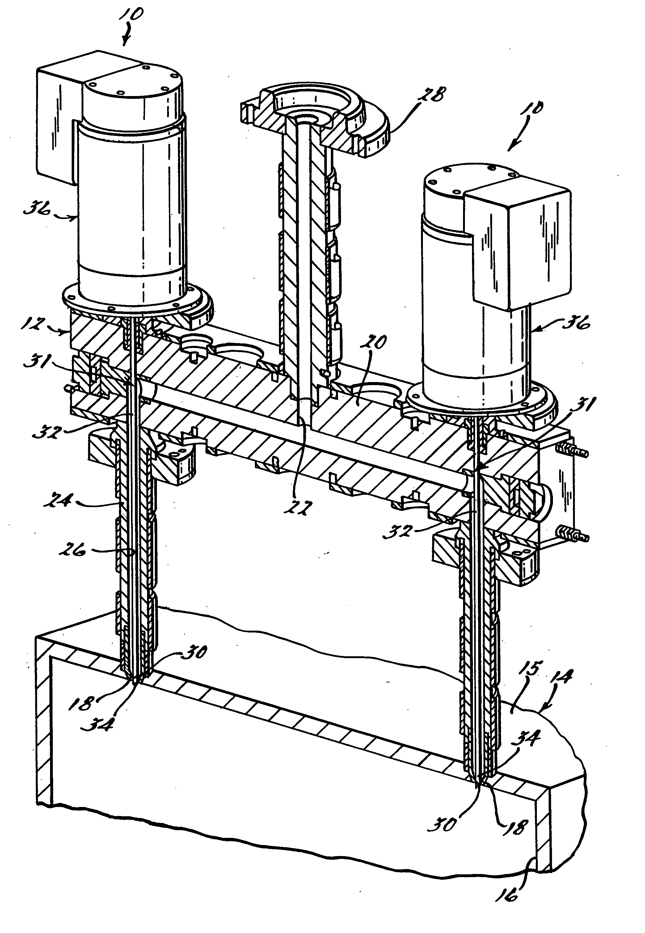
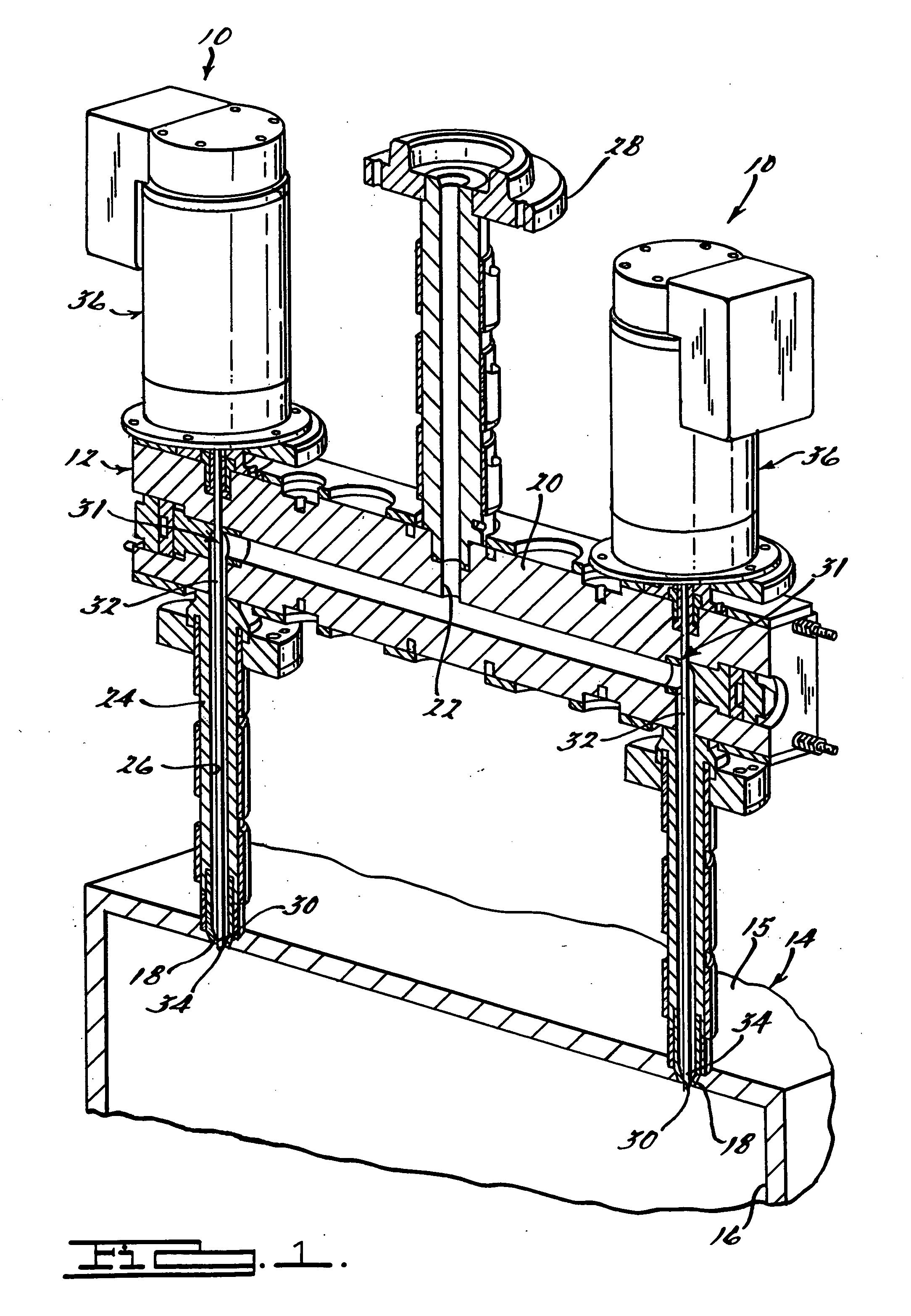
[0017] Referring to the drawings, and in particular FIG. 1, one embodiment of a valve gate assembly 10, according to the present invention, is shown for a manifold assembly, generally indicated at 12, and a mold, generally indicated at 14. The mold 14 has a first mold half 15 and a second mold half (not shown) defining a cavity 16 therein. The mold 14 also has at least one, preferably a plurality of openings 18 extending through the first mold half 15 and fluidly communicating with the cavity 16. It should be appreciated that, when a molten material (not shown) is introduced into the cavity 16 via the openings 18, the mold 14 contains the molten material, and when the molten material hardens or cures, it holds a shape similar to that of the cavity 16. It should also be appreciated that the mold 14 is conventional and known in the art.

[0018] The manifold assembly 12 includes a manifold 20 having a manifold flow passage 22. The manifold assembly 12 also includes as least one, prefer...


PUM

PropertyMeasurementUnit
shapeaaaaaaaaaa
pressureaaaaaaaaaa
flow rateaaaaaaaaaa

Abstract

A valve gate assembly for regulating a flow of molten material into a mold. The valve gate assembly includes a movable valve that can move between a fully closed position and a fully open position. The valve gate assembly further includes an actuating system operatively cooperating with the valve to move the valve and infinitely position the valve between the fully closed position and the fully open position.

Description

CROSS-REFERENCE TO RELATED APPLICATION [0001] The present application claims the priority date of copending U.S. Provisional Patent Application Ser. No. 60 / 519,312, filed Nov. 11, 2003.BACKGROUND OF THE INVENTION [0002] 1. Field of the Invention [0003] The present invention relates generally to valve gates and, more particularly, to a valve gate assembly for regulating a flow of molten material into a cavity of a mold. [0004] 2. Description of the Related Art [0005] Injection molding is a widely known manufacturing process used to produce a variety of parts. Injection molding involves introducing a molten material, for example a molten plastic or resin, into a cavity within a mold until the cavity is filled. The molten material hardens or cures in the mold in the shape of inner surfaces of the cavity. After the molten material hardens or cures, the hardened or cured material is removed from the cavity. [0006] For injection molding, a manifold is typically used for conveying molten m...

Claims


Application Information

Patent Timeline
Patent Type & Authority Applications(United States)
IPC IPC(8): B29CB29C45/28B29C45/76B29C48/92
CPCB29C45/281B29C45/76B29C2045/1793B29C47/92B29C2045/2865B29C2045/2872B29C2045/2824B29C45/20
Inventor TOOMAN, PATRICK A.CASEY, BRUCE
Owner PLASTIC ENG & TECHN SERVICES
Why Eureka
Try Eureka