
Mobile telephone set having the capability to quickly select optimum base station

Inactive Publication Date: 2005-05-12
NEC CORP
View PDF1 Cites 3 Cited by
  • Summary
  • Abstract
  • Description
  • Claims
  • Application Information

AI Technical Summary

Benefits of technology

[0014] It is therefore an object of the present invention to provide a mobile telephone set that is capable of quickly selecting a base station with which the mobile telephone set can communicate while the mobile telephone set is in motion, and is thus less liable to cause handovers.
[0016] Specific information specifying base stations is stored in advance by the memory means. If specific information from a base station detected by the detecting means is present in the specific information stored by the memory means, the base station corresponding to the specific information is selected as a base station to communicate with. In this manner, the mobile telephone set performs less operation to search for a nearby base station in switching between base stations, and can quickly select a base station. Therefore, the mobile telephone set is less liable to cause handovers, i.e., to have less switching between base stations.

Problems solved by technology

The time-consuming process poses problems when the portable telephone set is moving at a high speed.
Prior to the proposed mobile communication terminal device, it may not necessarily be possible to select a closest one of a plurality of base stations according to a desired communication system.
Therefore, it may take time for the disclosed mobile communication terminal device to select a base station that is located in an optimum position, and the disclosed mobile communication terminal device may possibly cause handovers.
Prior to the mobile body map matching apparatus disclosed in JP2000-213948A, conventional apparatus have suffered various problems.
For example, in indoor environments, walkers cannot be navigated because the GPS (Global Positioning System) technology is not available and map matching for the walkers is not established.
It is burdensome for walkers to carry a gyro unit for outdoor positional detection.
The position detecting technique based on an electric field intensity detects a position in a single electric field intensity measuring cycle, but the detected positional information is not highly reliable because the electric field intensity tends to change even when detected in the same position.
The presently available position detecting technique based on an electric field intensity is not effective if an electric field intensity from a base station cannot be measured.
Furthermore, the presently available position detecting technique based on an electric field intensity needs to have a position recognizing device such as a non-contact IC card or the like installed at a certain spot for recognizing the position of a walker in an indoor environment, and hence is expensive.
However, the disclosed mobile body map matching apparatus is merely capable of simply and accurately detecting the position of a walker, and is not designed to quickly select a base station while the mobile telephone set is in rapid motion.
The radio communication system disclosed in JP2001-309420A has been proposed in view of the problem that since a wired LAN (Local Area Network) has a standard communication rate of 10 Mbits / sec., the communication rate in a high-speed mobile environment is not sufficient to enjoy services available through the Internet.
The disclosed radio communication system is not designed to allow a mobile telephone set to quickly select a base station while the mobile telephone set is in motion.
However, the revealed mobile telephone display device is not designed to allow a mobile telephone set to quickly select a base station while the mobile telephone set is in motion.

Method used


Image

  • Mobile telephone set having the capability to quickly select optimum base station
  • Mobile telephone set having the capability to quickly select optimum base station
  • Mobile telephone set having the capability to quickly select optimum base station

Examples


Embodiment Construction

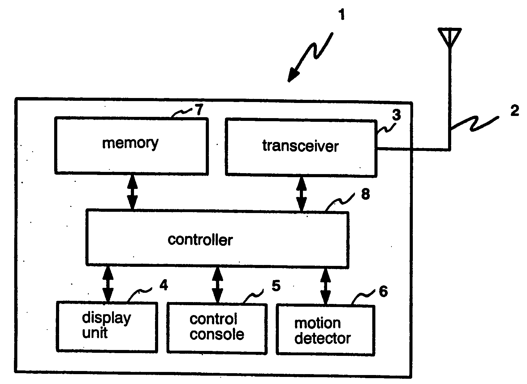
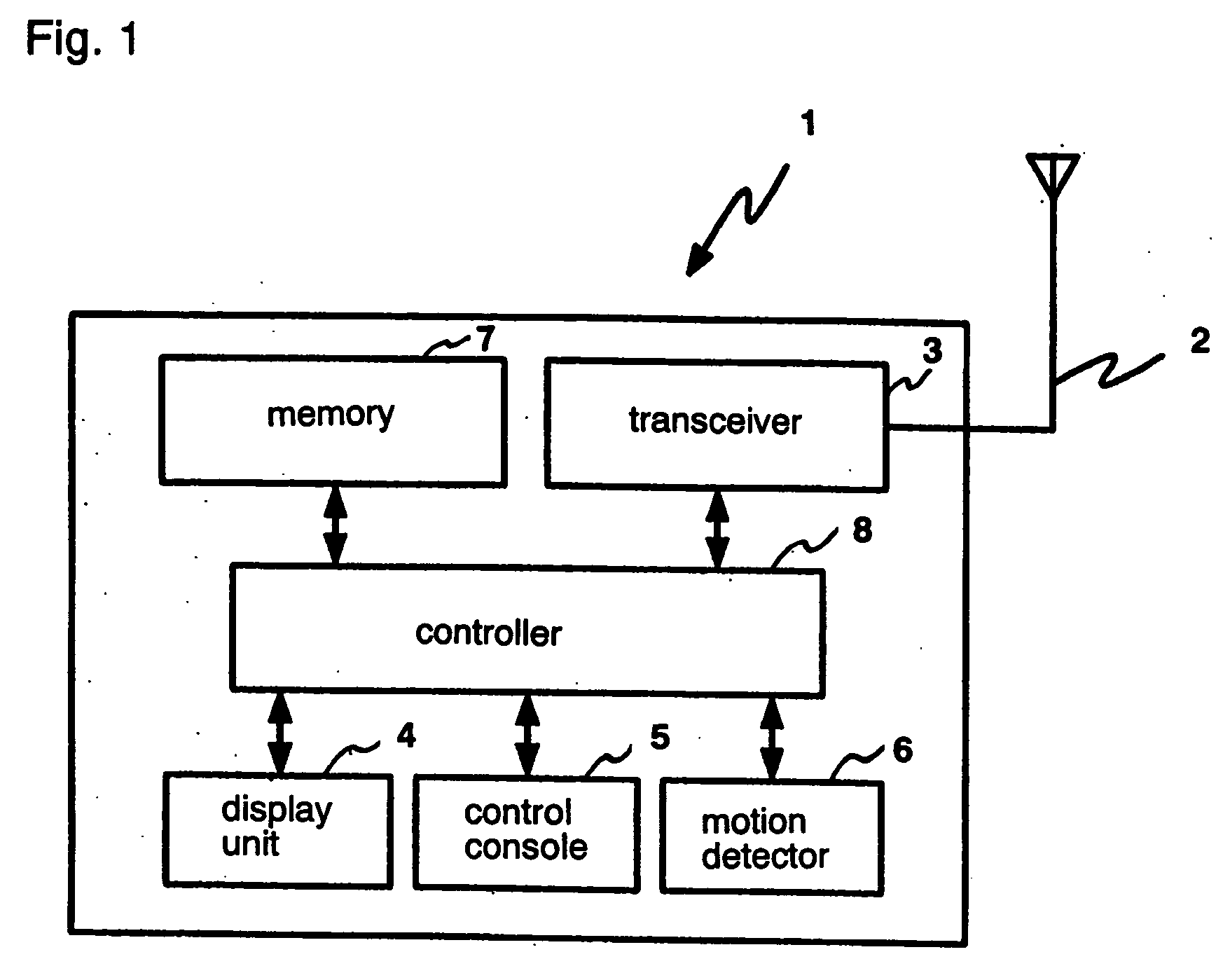
[0023] Referring now to FIG. 1, mobile telephone set 1 according to an embodiment of the present invention is a terminal unit such as a portable telephone set, an automobile telephone set, a PHS set, or the like, and has antenna 2, transceiver 3, display unit 4, control console 5, motion detector 6, memory 7, and controller 8.

[0024] Antenna 2 serves to receive radio signals. Transceiver 3 communicates with base stations (not shown) at a proper frequency. Display unit 4 comprises a liquid display panel or the like. Control console 5 comprises a ten-key pad, a power supply switch, and various selection keys. Motion detector 6 detects when mobile telephone set 1 is in motion.

[0025] Memory 7 stores respective items of specific information of base stations with which mobile telephone set 1 is to communicate, in the order of positions that mobile telephone set 1 successively takes when mobile telephone set 1 moves along each route. By way of example, as shown in FIG. 4, memory 7 stores ...


PUM


Abstract

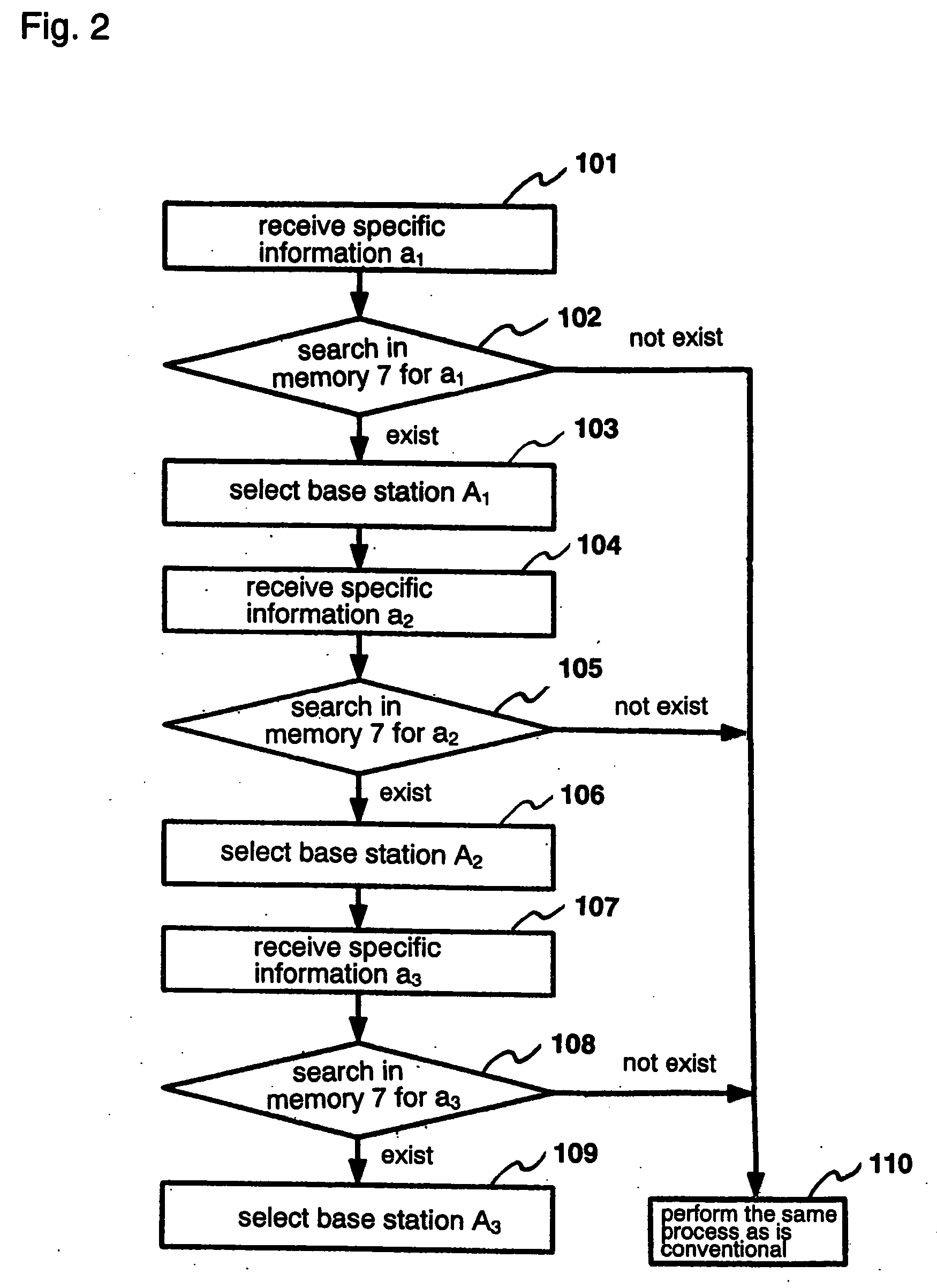
A mobile telephone set is capable of quickly selecting a base station with which the mobile telephone set can communicate while the mobile telephone set is in motion, and is thus less liable to cause handovers. The mobile telephone set has a memory for storing specific information specifying base stations. When a transceiver of the mobile telephone set detects specific information from a base station, a controller of the mobile telephone set reads the specific information from the memory. If the detected specific information from the base station is included in the specific information read from the memory, then the controller selects the detected base station corresponding to the specific information. If the detected specific information from the base station is not included in the specific information read from the memory, then the controller selects a base station providing a highest electric field intensity.

Description

BACKGROUND OF THE INVENTION [0001] 1. Field of the Invention [0002] The present invention relates to a mobile telephone set, and more particularly to a mobile telephone set that is capable of quickly selecting a base station which is most relevant while the mobile telephone set is in motion. [0003] 2. Description of the Related Art [0004] Heretofore, the operation of conventional portable telephone sets to wait for a call and select a base station to communicate with is started by searching for a possible frequency for an annunciation signal from a base station. Such a process takes time until a candidate is found. The time-consuming process poses problems when the portable telephone set is moving at a high speed. Therefore, it is necessary for the portable telephone set to quickly select a base station. [0005] Various proposals have been made to meet such a requirement. [0006] For example, JP7-143544A proposes a mobile communication terminal device for performing communications com...

Claims


Application Information

Patent Timeline
IPC IPC(8): H04W4/02H04W36/32H04W48/20
CPCH04W4/02H04W48/20H04W36/32H04W36/324
Inventor OGATA, SHIGERU
Owner NEC CORP
Learn More