Roll-pitch-roll wrist methods for minimally invasive robotic surgery

a robotic surgery and wrist technology, applied in the field of teleoperator methods and equipment, can solve the problem that the operator is not provided with a sense of being present at the worksite, and achieve the effect of enhancing the operator's sense of presen

Inactive Publication Date: 2005-05-12
SRI INTERNATIONAL
View PDF89 Cites 59 Cited by
  • Summary
  • Abstract
  • Description
  • Claims
  • Application Information

AI Technical Summary

Benefits of technology

[0008] An object of this invention is the provision of an improved teleoperator system and method which include an improved viewing system to enhance the operator's sense of presence at remote manipulators controlled by the operator from a remote location.
[0009] An object of this invention is the provision of an improved teleoperator system and method of the above-mentioned type wherein an image of manipulator end effectors for viewing by the operator are sensed by the operator as comprising an integral part of hand-controllers used by the operator to control the end effectors, thereby giving the operator a strong sense of presence at the worksite.
[0011] The present invention includes manipulators located at a worksite and which are controlled by hand-operated means at a remote operator control station. End effectors at the manipulators are used for manipulating objects located in a workspace at the worksite, and force-torque feedback is employed for transmitting back to the operator mechanical resistance encountered by the end effectors. Stereographic visual display means provide the operator with an image of the workspace. In accordance with the present invention, the image is located adjacent the hand-operated means so that the operator looks in the direction of the hand-operated means for viewing the image adjacent the hand-operated means. Either a real or virtual image of the workspace may be provided adjacent the hand-operated means. Display means for display of a real image may be located adjacent the hand-operated means for direct viewing of the real image by the operator. For display of a virtual image of the workspace, a mirror is located between the operator's eyes and the hand-operated means. In this case, display means provide a real image which is inverted from top to bottom, which inverted image is viewed via the mirror, which mirror inverts the image and provides the operator with a virtual image of the workspace, which appears to be located adjacent the hand-operated means. By locating the image of the workspace adjacent the hand-operated means the operator is provided with a sense that the end effectors and hand-operated means are substantially integral despite the fact the end effectors are located at the worksite and the hand-operated means are located at the remote operator's station. A stereophonic sound system may be included to provide the operator with stereophonic sound from the worksite. Video camera means are provided for viewing the workspace from which an image of the workspace is obtained. Various other sensors and associated responders may be located at the worksite and operator's station, respectively, for transmission of pressure, tactile, heat, vibration and similar information for enhanced telepresence operation.

Problems solved by technology

Even though the operator of prior art manipulators is provided with a stationary three-dimensional image of the workspace, and manual controllers for control of the manipulators are provided with feedback, the operator is not provided with a sense of actually being present at the worksite.

Method used


Image

  • Roll-pitch-roll wrist methods for minimally invasive robotic surgery
  • Roll-pitch-roll wrist methods for minimally invasive robotic surgery
  • Roll-pitch-roll wrist methods for minimally invasive robotic surgery

Examples


Embodiment Construction

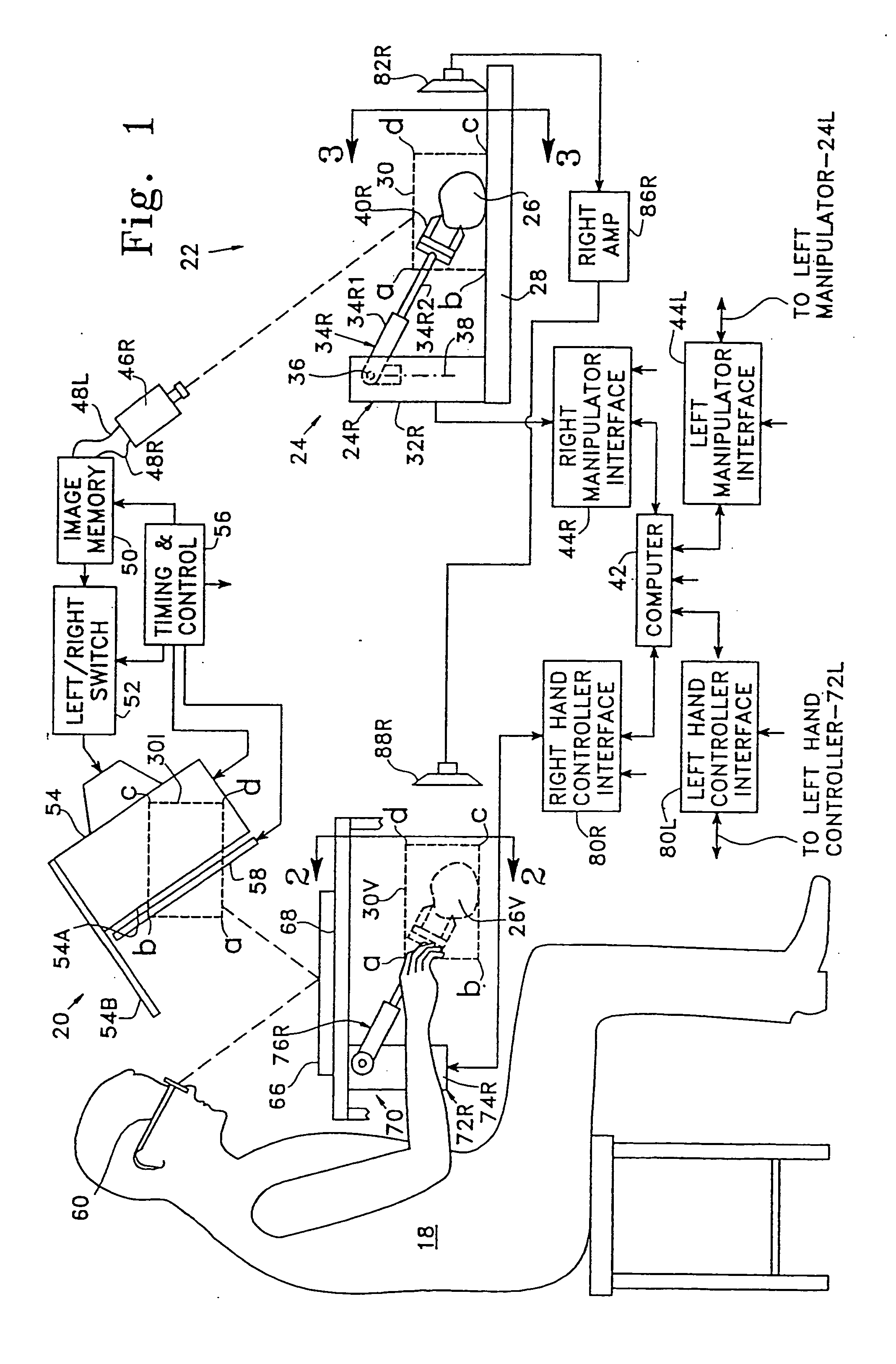
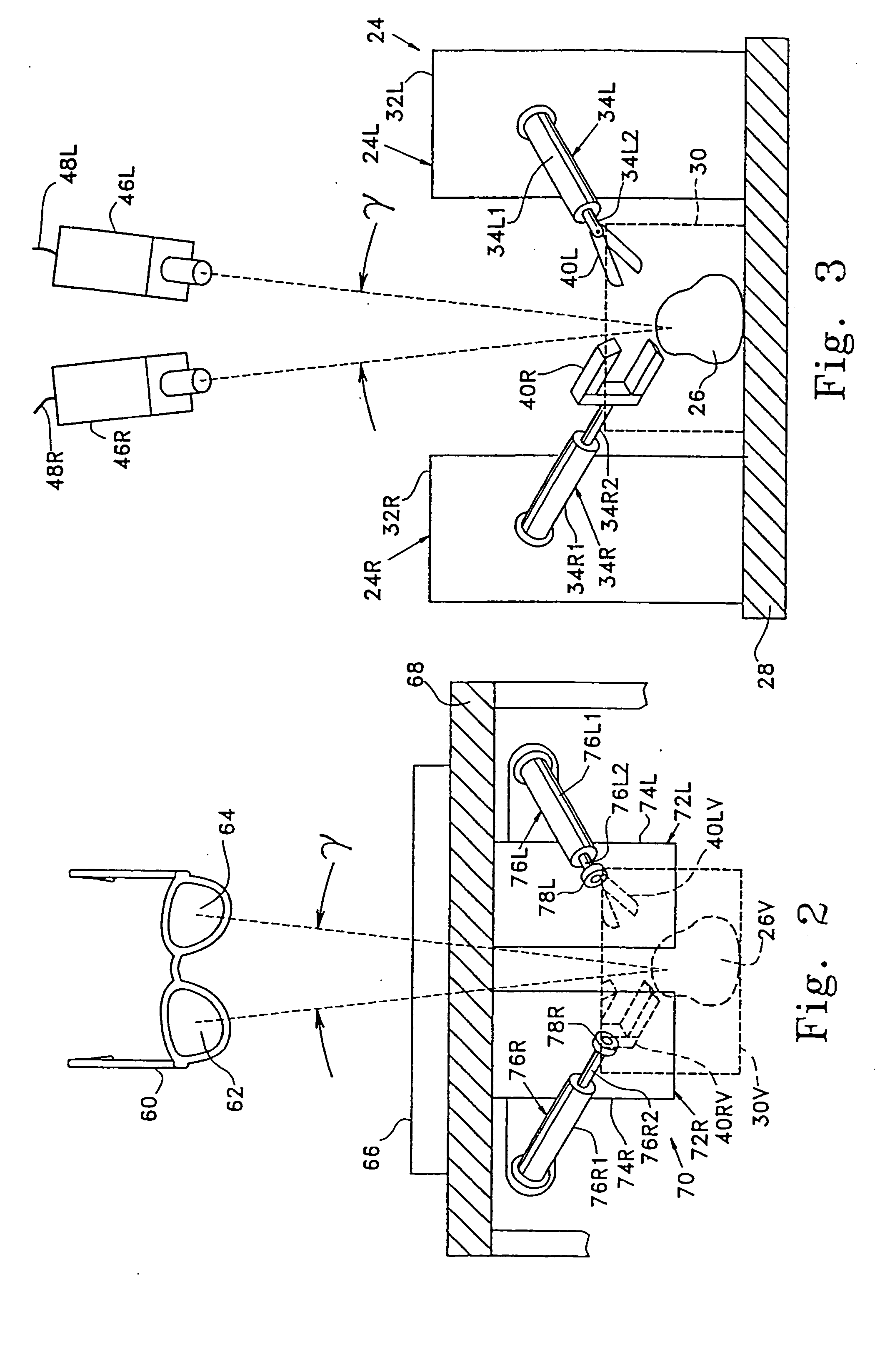
[0027] Reference now is made to FIGS. 1-3 wherein the teleoperator system is shown to include an operator's station 20 (FIGS. 1 and 2) and worksite 22 (FIGS. 1 and 3). An operator 18 at the operator's station controls manipulator means 24 at the remote worksite. Manipulator means 24, comprising right and left manipulators 24R and 24L, respectively, are used for manipulating objects, such as object 26 which is shown located on a platform, or base, 28 within a workspace 30 shown in broken lines. For purposes of illustration only, and not by way of limitation, the right manipulator 24R is shown to comprise a housing 32R affixed to base 28 and from which housing a telescopic arm 34R extends. The inner end 34R1 of arm 34R is mounted for pivotal movement in any pivotal direction using conventional mounting means. For example, the inner end of arm 34R may be mounted for pivotal movement about a horizontal pivot axis 36 which pivot axis, in turn, is adapted for pivotal movement about vertic...


PUM


Abstract

A teleoperator system with telepresence is shown which includes right and left hand controllers (72R and 72L) for control of right and left manipulators (24R and 24L) through use of a servomechanism that includes computer (42). Cameras (46R and 46L) view workspace (30) from different angles for production of stereoscopic signal outputs at lines (48R and 48L). In response to the camera outputs a 3-dimensional top-to-bottom inverted image (30I) is produced which, is reflected by mirror (66) toward the eyes of operator (18). A virtual image (30V) is produced adjacent control arms (76R and 76L) which is viewed by operator (18) looking in the direction of the control arms. Use of the teleoperator system for surgical procedures also is disclosed.

Description

CROSS-REFERENCES TO RELATED APPLICATIONS [0001] This application is a continuation of U.S. patent application Ser. No. 08 / 709,930 filed Sep. 9, 1996, which is a continuation of 07 / 823,932 filed Jan. 21, 1992 (now abandoned), the full disclosures of which are incorporated herein by reference.STATEMENT AS TO RIGHTS TO INVENTIONS MADE UNDER FEDERALLY SPONSORED RESEARCH OR DEVELOPMENT [0002] NOT APPLICABLE REFERENCE TO A “SEQUENCE LISTING,” A TABLE, OR A COMPUTER PROGRAM LISTING APPENDIX SUBMITTED ON A COMPACT DISK [0003] NOT APPLICABLE FIELD OF THE INVENTION [0004] This invention relates generally to teleoperator method and apparatus, and particularly to those which include means for providing the operator of remote apparatus with the same sense as working directly with his hands at the worksite. BACKGROUND OF THE INVENTION [0005] Teleoperating, which is well known, includes the human performance of tasks at a remote location using manipulators. Telepresense includes providing the tele...

Claims


Application Information

Patent Timeline
Patent Type & Authority Applications(United States)
IPC IPC(8): A61B17/00A61B19/00B25J3/04B25J19/02H04N13/239
CPCA61B1/00193H04N13/0497A61B19/22A61B19/52A61B19/5212A61B19/5225A61B2019/2211A61B2019/2223A61B2019/223A61B2019/2234A61B2019/2249A61B2019/2292A61B2019/2296A61B2019/464A61B2019/5227B25J3/04B25J19/023H04N13/0055H04N13/0059H04N13/0239H04N13/0246H04N13/0296H04N13/0434H04N13/0438A61B17/00234A61B90/36B25J13/025A61B2090/064A61B34/70A61B2034/301A61B90/361A61B34/37A61B34/35A61B2034/305A61B34/72A61B34/76A61B34/77A61B90/37A61B2090/371H04N13/337H04N13/341H04N13/194H04N13/189H04N13/246H04N13/296H04N13/239H04N13/398
Inventor GREEN, PHILIP S.
Owner SRI INTERNATIONAL
Why Eureka
Try Eureka