Multiprocessor system

a multi-processor system and cache memory technology, applied in the direction of memory adressing/allocation/relocation, instruments, digital computers, etc., can solve the problem of coherence control of cache memories, so-called cache coherence control, and slow memory access latency during access from a cpu to a main storage. problem, the effect of reducing the number of caches

Inactive Publication Date: 2005-05-12
HITACHI LTD
View PDF0 Cites 21 Cited by
  • Summary
  • Abstract
  • Description
  • Claims
  • Application Information

AI Technical Summary

Benefits of technology

[0015] A multiprocessor system that allows dynamic setting of partitions and simultaneous achieveme

Problems solved by technology

Meanwhile, the improvement of the memory access latency during access from a CPU to a main storage is slow when viewed in terms of absolute time.
In this context, the access latency tends to become a bottleneck in performance improvement.
When multiple CPUs each having a cache memory share a main storage in this way, coherence control of the cache memories, so-called cache coherence control, becomes a problem.
During the above-mentioned cache coherence control using a bus, cache coherence control requests

Method used


Image

  • Multiprocessor system
  • Multiprocessor system
  • Multiprocessor system

Examples


embodiment 1

[0030] The operation of a multiprocessor system according to the present invention is outlined below first, and then the operation of this multiprocessor system is detailed below in the following order: [0031] (1) Coherence control through a bus [0032] (2) Coherence control through a NUMA network [0033] (3) Bus connecting change process

[Operational Outline]

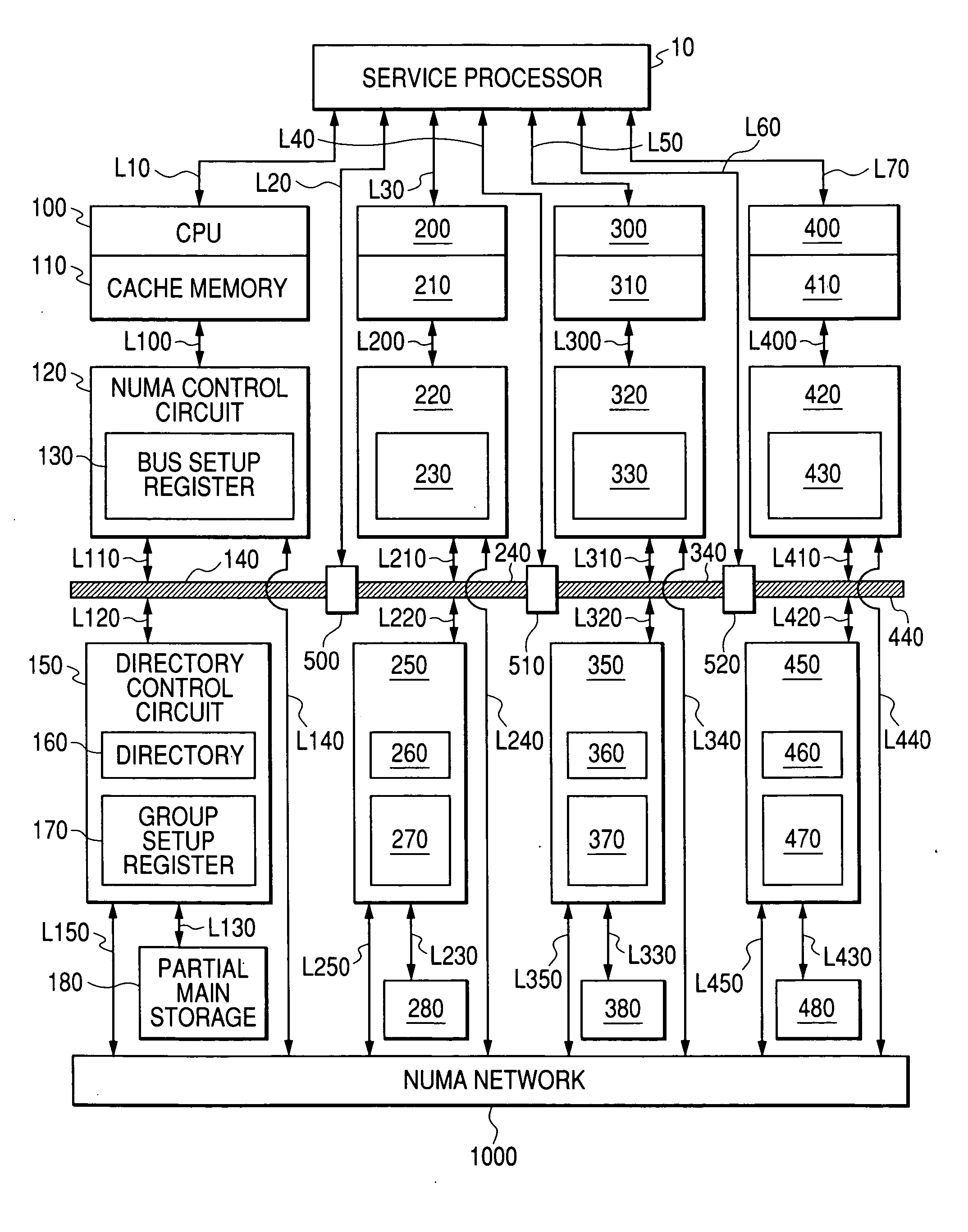
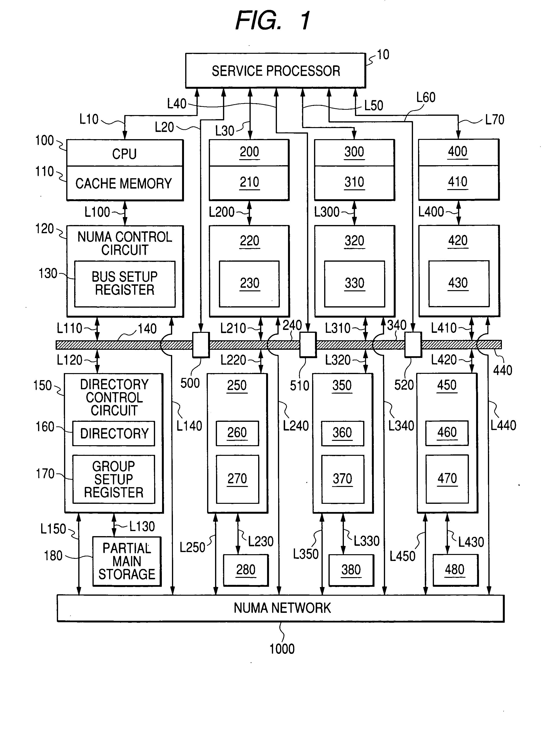
[0034] Using FIG. 1, this section outlines the operation of the multiprocessor system according to the present invention. The description below assumes that bus splitting / connecting circuits 500, 510, and 520 are initially set so that the circuits 500 and 520 are in a connected state and, the circuit 510, in a split state. In other words, it is to be assumed that although CPUs 100 and 200 are bus-connected and CPUs 300 and 400 are also bus-connected, the two sets of CPUs themselves are isolated from each other.

[0035] In this state, a cache coherence request issued from, for example, the CPU 100 can be transmitted to the CPU 200...

embodiment 2

[0106] Although Embodiment 1 presupposes the existence of a special NUMA network 1000 for NUMA control, Embodiment 2 described below assumes that packets for the NUMA protocol are also executed via a bus, instead of the NUMA network 1000.

[0107] A system configuration of Embodiment 2 is shown in FIG. 14. Three differences from the configuration of Embodiment 1 as shown in FIG. 1 exist.

[0108] A first difference exists in that the bus splitting / connecting circuits 500, 510, and 520 are substituted by pass filter circuits 505, 515, and 525, respectively. For packets other than NUMA control packets, the pass filter circuits 505, 515, and 525 function similarly to the bus splitting / connecting circuits 500, 510, and 520. In other words, depending on its setting by the service processor 10, each pass filter circuit permits or prohibits passage of a packet. However, packets for NUMA control are always permitted to pass.

[0109] A second difference is as follows: in Embodiment 1, a fetch req...


PUM


Abstract

A splittable/connectible bus 140 and a network 1000 for transmitting coherence transactions between CPUs are provided between the CPUs, and a directory 160 and a group setup register 170 for storing bus-splitting information are provided in a directory control circuit 150 that controls cache invalidation. The bus is dynamically set to a split or connected state to fit a particular execution form of a job, and the directory control circuit uses the directory in order to manage all inter-CPU coherence control sequences in response to the above setting, while at the same time, in accordance with information of the group setup register, omitting dynamically bus-connected CPU-to-CPU cache coherence control, and conducting only bus-split CPU-to-CPU cache coherence control through the network. Thus, decreases in performance scalability due to an inter-CPU coherence-processing overhead are relieved in a system having multiple CPUs and guaranteeing inter-CPU cache coherence by use of hardware.

Description

CLAIMS OF PRIORITY [0001] The present application claims prority from Japanese application JP 2003-379294 filed on Nov. 10, 2003, the content of which is hereby incorporated by reference into this application. FIELD OF THE INVENTION [0002] The present invention relates to inter-CPU coherence control of cache memories in a shared-memory-type parallel computer having multiple CPUs and sharing a main storage between the CPUs. More particularly, the invention relates to an inter-CPU cache coherence control scheme. BACKGROUND OF THE INVENTION [0003] Thanks to the progress of device technology, the operating frequencies of CPUs are rapidly improving. Meanwhile, the improvement of the memory access latency during access from a CPU to a main storage is slow when viewed in terms of absolute time. This is because the memory access latency is restricted by the physical distance from the CPU to the main storage and by the characteristics of the main storage element. This means that the access l...

Claims


Application Information

Patent Timeline
IPC IPC(8): G06F12/08G06F15/167G06F15/177
CPCG06F12/0813G06F12/0831G06F12/0817
Inventor SUKEGAWA, NAONOBU
Owner HITACHI LTD
Why Eureka
Try Eureka