Dual and hybrid EGR systems for use with turbocharged engine

a hybrid and turbocharged technology, applied in the direction of machines/engines, mechanical equipment, non-fuel substance addition to fuel, etc., can solve the problems of inability to meet future emission requirements, difficult than ever to match the operation of the turbocharger to provide optimum engine performance, and inability to meet current egr technology. to meet such requirements

Active Publication Date: 2005-05-19
GARRETT TRANSPORATION I INC
View PDF49 Cites 98 Cited by
  • Summary
  • Abstract
  • Description
  • Claims
  • Application Information

AI Technical Summary

Benefits of technology

[0010] The present invention is of an exhaust gas recirculation (EGR) system comprising an engine having an intake manifold and an exhaust manifold; a turbocharger with at least one compressor stage; a first exhaust gas bypass stream connected to receive exhaust gas upstream of the turbocharger; a first control valve connected in the first exhaust gas bypass stream to control the amount of exhaust gas received from the exhaust manifold; a second exhaust gas bypass stream connected to receive exhaust gas

Problems solved by technology

While such conventional EGR systems may be sufficient for meeting today's emissions regulations for certain application, future emission requirements will be more stringent and the current state of the EGR technology will not be able to meet such requirements.
When looking at turbocharged engine applications,

Method used


Image

  • Dual and hybrid EGR systems for use with turbocharged engine
  • Dual and hybrid EGR systems for use with turbocharged engine
  • Dual and hybrid EGR systems for use with turbocharged engine

Examples


first embodiment

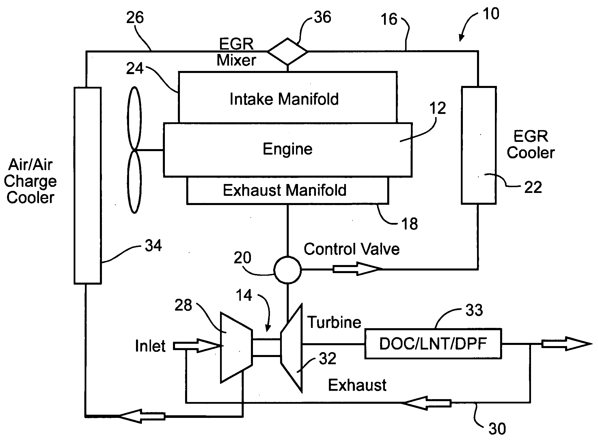
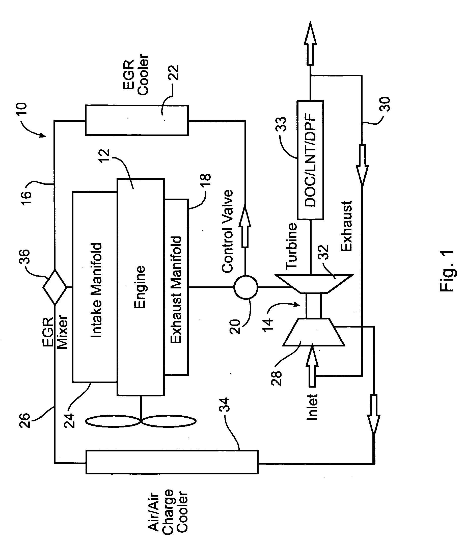
[0042]FIG. 1 illustrates a first embodiment dual EGR system 10 of this invention comprising engine 12 and turbocharger 14 connected thereto. In the example illustrated, the engine 12 is of an inline piston configuration, however EGR system 10 will work with any engine configuration. As used herein, the term “dual” is understood to refer to the fact that two EGR streams are being provided to the engine. First EGR stream 16 is provided from engine exhaust manifold 18 and is controlled via control or EGR valve 20. Cooler 22 is used to cool the first EGR stream before introduced into engine intake manifold 24. Exhaust gas from a second EGR stream is mixed with intake air and pressurized by turbocharger compressor 28. The exhaust gas for the second EGR stream is provided to an inlet end of the compressor via exhaust bypass stream 30 exiting the turbocharger turbine 32. The exhaust bypass is taken downstream of exhaust after-treatment 33, and air-to-air charge cooler 34 is used to cool pr...

second embodiment

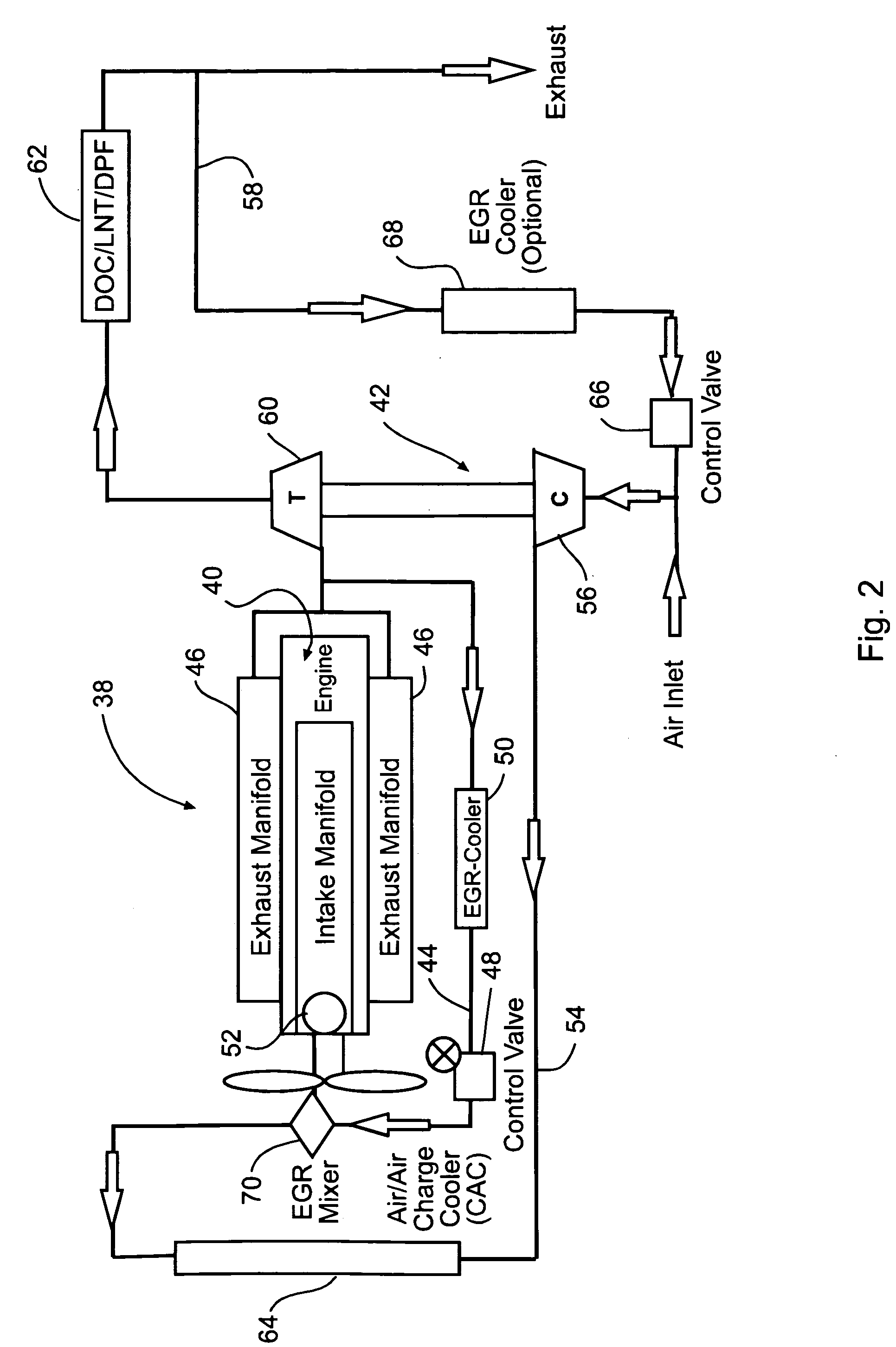
[0044]FIG. 2 illustrates a second embodiment dual EGR system 38 of this invention comprising engine 40 and turbocharger 42 connected thereto. In the example illustrated, engine 40 is of a V-8 piston configuration, however EGR system 38 will work with any engine configuration. First EGR stream / LPL 44 is provided from engine exhaust manifolds 46 and is controlled via first control or EGR valve 48. Cooler 50 is used to cool the first EGR stream before introduced into engine intake manifold 52. Second EGR stream / HPL 54 is provided with pressurized intake air provided by turbocharger compressor 56. The exhaust gas for the second EGR stream is provided to an inlet end of the compressor via exhaust bypass stream 58 exiting turbocharger turbine 60. The exhaust bypass is taken downstream of exhaust after-treatment 62, and air-to-air charge cooler 64 is used to cool the pressurized intake air and second EGR stream before introduction into the intake manifold. Second control or EGR valve 66 ca...

third embodiment

[0046]FIG. 3 illustrates a third embodiment dual EGR system 72 that is in many respects similar to that described above and illustrated in FIG. 2, except that the turbocharger 74 includes a compressor section 76 comprising a double sided or two-stage compressor. First compressor 78 is a low pressure compressor that receives a mix of intake air and EGR from exhaust bypass 82 and pressurizes the same before routing to second compressor 80 that is a high pressure compressor and that operates to provide a final desired boosting pressure for introduction of the mixed intake air and EGR into the engine. Charge air cooler 84 may optionally be used between the first and second compressor stages. Like the embodiment illustrated in FIG. 2, first / LPL 86 and second / HPL EGR streams 88 are operated to provide desired cooled EGR for mid / full load operation, and uncooled EGR for idle / low load operation.

[0047]FIG. 4 illustrates a fourth embodiment dual EGR system 90 that is in many respects similar ...


PUM


Abstract

EGR systems for an internal combustion engine configured to operate using multiple-staged turbochargers, or a pair of single stage turbochargers, to provide exhaust gas recirculation to meet emissions requirements while not affecting engine performance. One or two EGR loops operating at low, intermediate, or high pressures may be employed. EGR exhaust gases may be taken directly from the exhaust manifold, or after the exhaust stream has passed through a turbocharger turbine. EGR exhaust gases may be injected at an intermediate pressure between stages of a multiple stage turbocharger, or alternatively between a low pressure turbocharger compressor and high pressure turbocharger compressor, before being boosted to a pressure high enough to ensure the desired mass flow to the engine and delivered to the intake manifold. Intake air may be pressurized prior to mixing with the EGR exhaust gases.

Description

CROSS-REFERENCE TO RELATED APPLICATIONS [0001] This application claims the benefit of the filing of U.S. Provisional Patent Application Ser. No. 60 / 425,933 entitled “Dual and Hybrid EGR Systems for Use With Turbocharged Engines”, filed on Nov. 13, 2002, and the specification thereof is incorporated herein by reference.BACKGROUND OF THE INVENTION [0002] 1. Field of the Invention (Technical Field): [0003] The present invention relates generally to the field of gasoline and diesel-powered internal combustion engines that make use of exhaust gas recirculation (EGR) systems and, more particularly, to dual and hybrid EGR systems that are specially adapted for use with turbocharged internal combustion engines. [0004] 2. Description of Related Art [0005] EGR is a known method that is currently employed with internal combustion gasoline and diesel-powered engines for reducing NOx emissions. Conventional EGR systems work by taking a by-pass stream of engine exhaust gas from an engine exhaust ...

Claims


Application Information

Patent Timeline
IPC IPC(8): F02B29/04F02B37/007F02B37/013F02B47/08F02M25/07
CPCF02B29/0406F02B37/001F02B37/004F02B37/007F02B37/013F02M25/0707Y02T10/144F02M25/0711F02M25/0718F02M25/0732F02M25/074F02M25/0744Y02T10/121F02M25/0709F02M26/05F02M26/06F02M26/08F02M26/15F02M26/24F02M26/35F02M26/38Y02T10/12
Inventor BROOKSHIRE, DENNISARNOLD, STEVEN DON
Owner GARRETT TRANSPORATION I INC
Why Eureka
Try Eureka