

Method for making optical fiber preform having ultimately low pmd through improvement of ovality
- Summary
- Abstract
- Description
- Claims
- Application Information
AI Technical Summary
Benefits of technology
Problems solved by technology
Method used
Image

Examples
experimental example
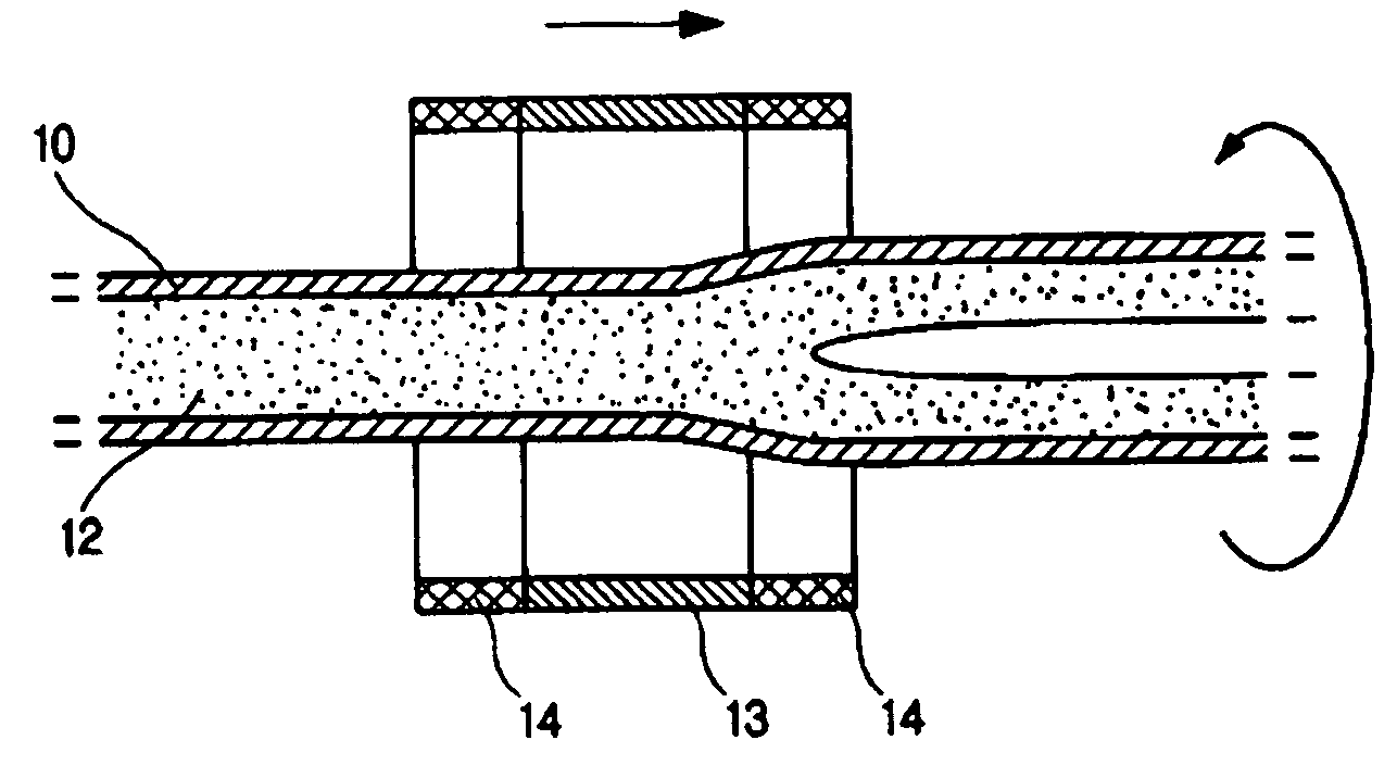
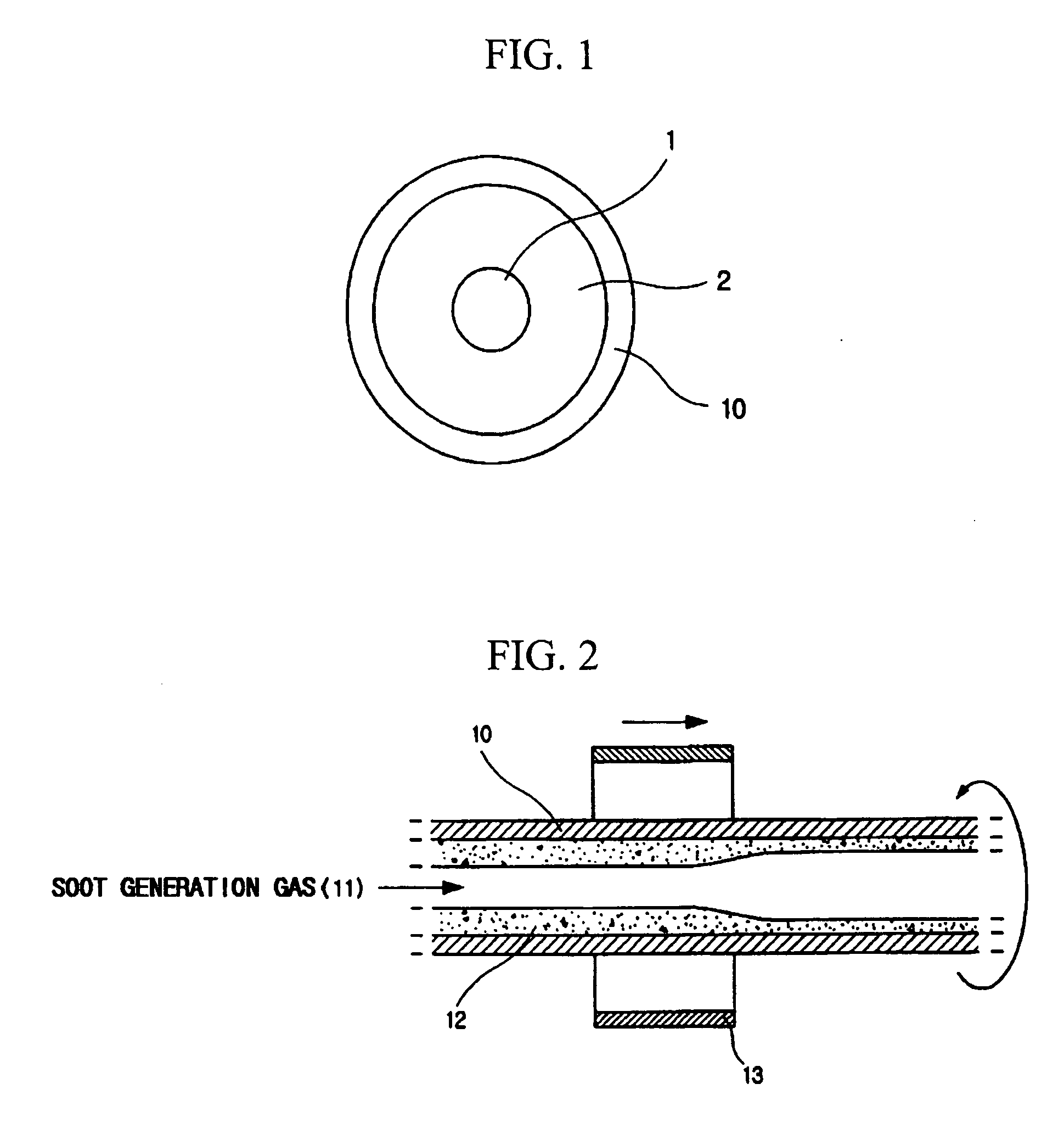
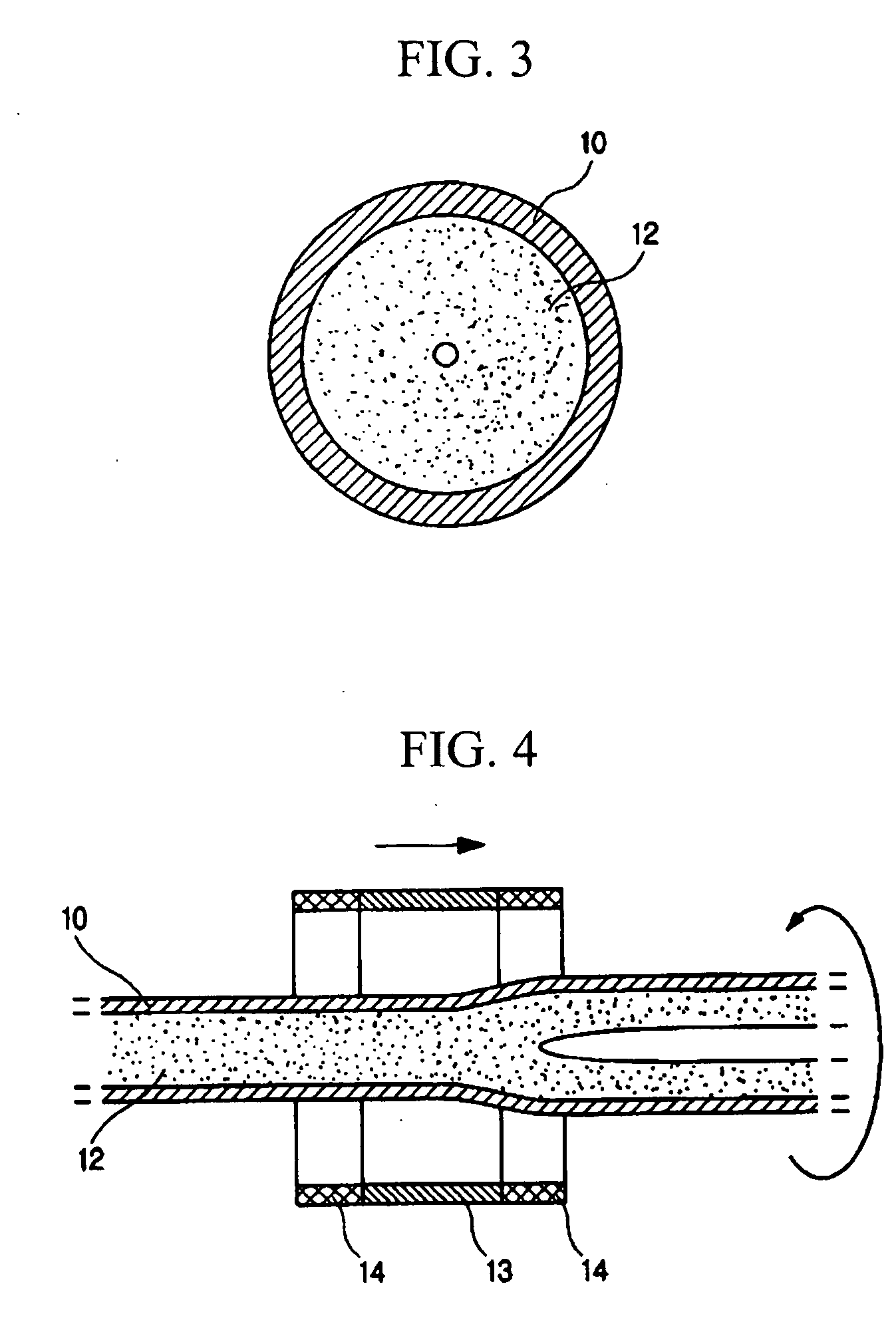
[0049] In this experiment example, the collapsing step is repeated three times under the condition that the tube rotates as much as 20 rpm and main factors such as a difference between inner and outer pressures and a flow rate of oxygen gas in the tube are differently set at each collapsing step as shown in Table 1.
TABLE 1Difference betweenFlow rate ofTemperatureinner & outer pressuresoxygen gasRate of collapseOvality(° C.)(mmWC)(sccm)(mm / min)(%)1st20001030000.05˜0.060.92nd2150515000.03˜0.040.63rd23000200.01˜0.020.2
[0050] The ovality of an optical fiber is improved even though the tube rotates at 30 or 40 rpm.
[0051] On the other hand, in order to eliminate or minimize a layer having a refractive index defect in the tube by etching after the collapsing process, an inside surface area of the tube should be minimized so as to prevent GeO2 from volatilizing. For this reason, a size of the empty area in the tube is made to about 2 to 4 mm after the collapsing steps, namely just before...
PUM
| Property | Measurement | Unit |
|---|---|---|
| Temperature | aaaaa | aaaaa |
| Diameter | aaaaa | aaaaa |
| Length | aaaaa | aaaaa |
Abstract
Description
Claims
Application Information