
Method of manufacturing a tubular storage assembly

a manufacturing method and storage assembly technology, applied in the direction of packaging, other accessories, clamping mechanisms, etc., can solve the problems of unattractiveness for most users, poor tubular shape, and relatively thin shell material, so as to facilitate the maintenance of its tubular shape and relation

Inactive Publication Date: 2005-05-19
MASSO ROBIN
View PDF27 Cites 4 Cited by
  • Summary
  • Abstract
  • Description
  • Claims
  • Application Information

AI Technical Summary

Benefits of technology

[0007] In this regard, the present invention provides a tubular storage assembly that is manufactured in a novel manner that allows the use of a heavy weight shell material. The shell material it self is quite durable and is fashioned in such a manner utilizing the method of the present invention in order to produce a structure that facilitates the maintenance of its tubular shape and relation throughout the life of the product without the de-lamination issues encountered in the prior art.
[0008] In the process of the present invention, a sheet of heavy weight shell material is provided. The material is preferably a full weight leather hide although other materials such as a heavy canvas, a denim or any other suitable material are also anticipated under the present disclosure. The sheet is formed into the desired shape to create the outer wall of the tube. Typically this forming step would involve stamping or cutting of the sheet material. Two opposing edges of the sheet are cut to form a matching edge seam. A two part linear fastener such as a zipper, hook and loop, a row of buttons, or any other suitable system is then attached wherein one half of the system is attached to one side of the seam and the other half of the system is attached to the second opposing side of the seam. The shell is then rolled into a tubular shape by bringing the opposing sides of the seam together and connecting the fasteners provided thereon. The seam is then covered by permanently adhering a cover strip over the seam to conceal the linear fastener system and give the tube a uniform appearance. End caps can then be added either by stitching or by using a slide on type cap. Finally, a plastic tube or another liner material may be included to enhance the rigidity of the tube walls and provide a low friction surface to facilitate the insertion or withdrawal of documents stored therein.
[0009] It can be appreciated that a distinct advantage provided by the present invention is that the fastener system can be stitched into the shell wall while the wall is flat. This is a great improvement wherein stitching of a tubular assembly is nearly impossible when using relatively rigid materials.
[0010] Accordingly, it is an object of the present invention to provide a novel construction for a tubular storage assembly. It is a further object of the present invention to provide a novel construction for a tubular storage assembly that includes an outer shell that is formed from a durable heavyweight material. It is yet a further object of the present invention to provide a tubular storage assembly and a method of manufacturing the same that provides for a heavyweight exterior shell that is easily fabricated and assembled while being resistant to de-lamination during usage.

Problems solved by technology

While theses plastic tubes have been effective in providing the necessary protection, most users consider them to be quite unattractive.
The difficulty in the prior art is that in order to form a tube, the materials must be light weight.
The drawback to this construction is that the shell material is relatively thin and is subject to rapid wear and failure.
Due to the nature of this construction, durability of the finished product is rather low.

Method used


Image

  • Method of manufacturing a tubular storage assembly
  • Method of manufacturing a tubular storage assembly
  • Method of manufacturing a tubular storage assembly

Examples


Embodiment Construction

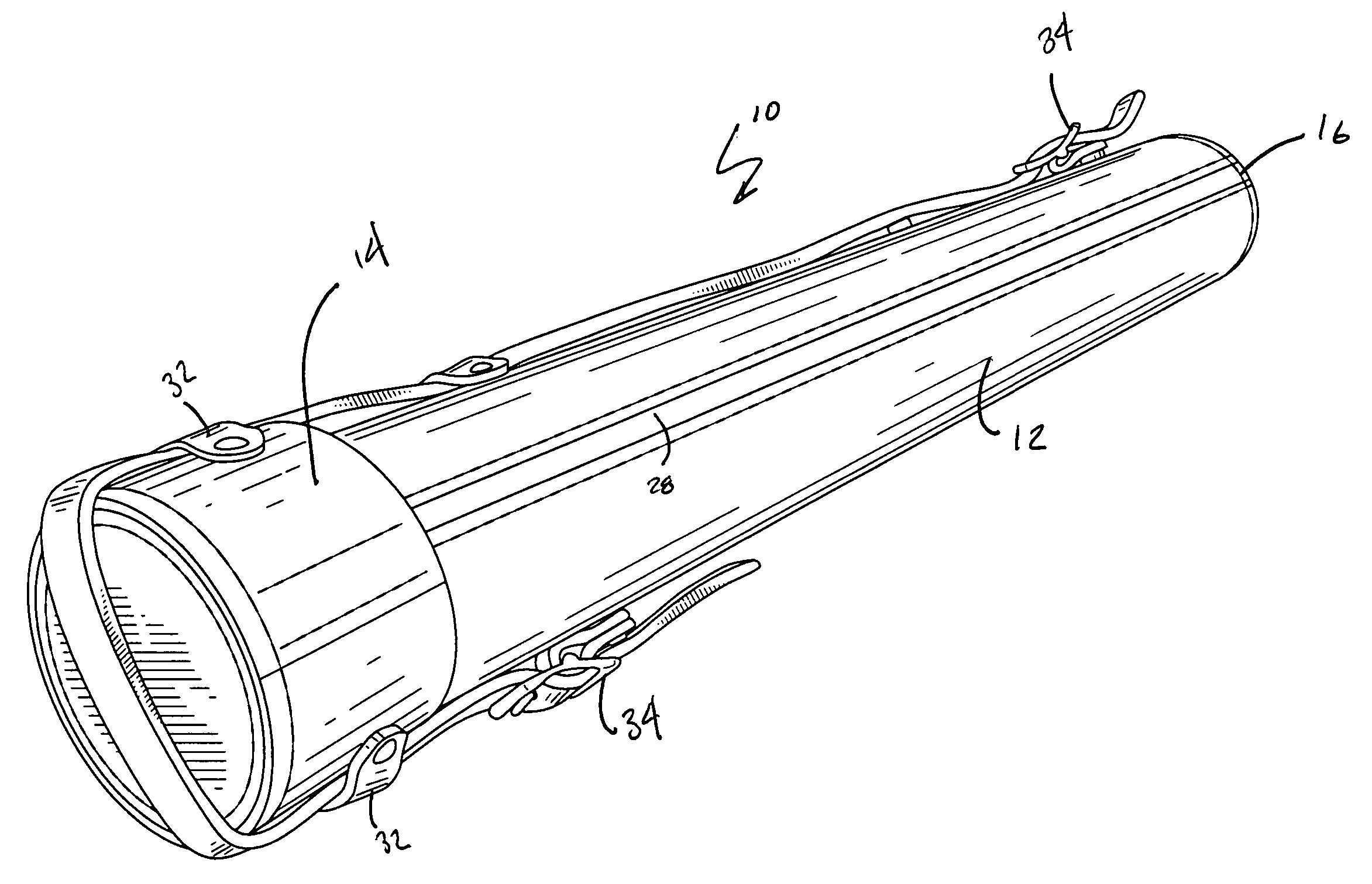
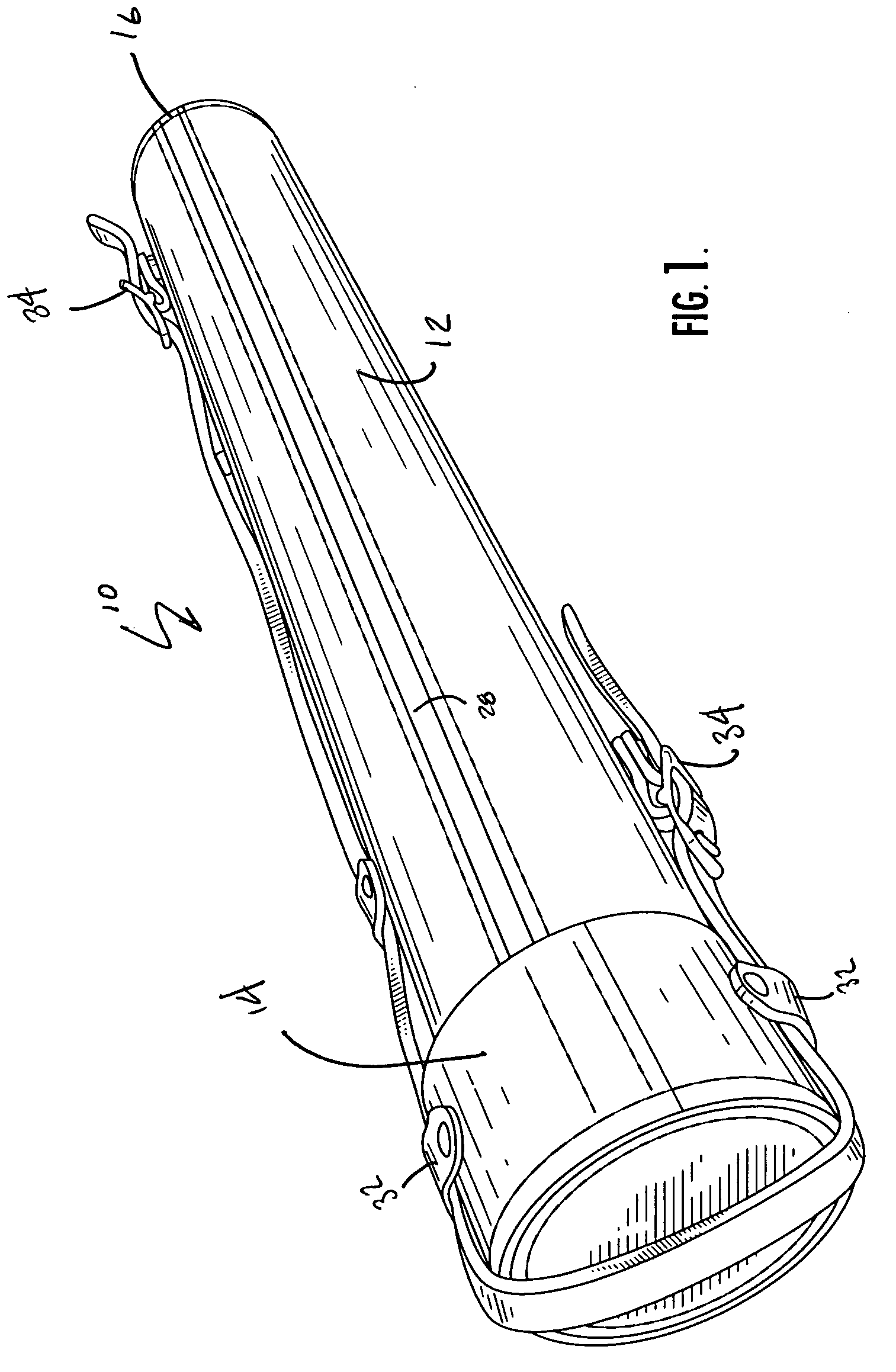
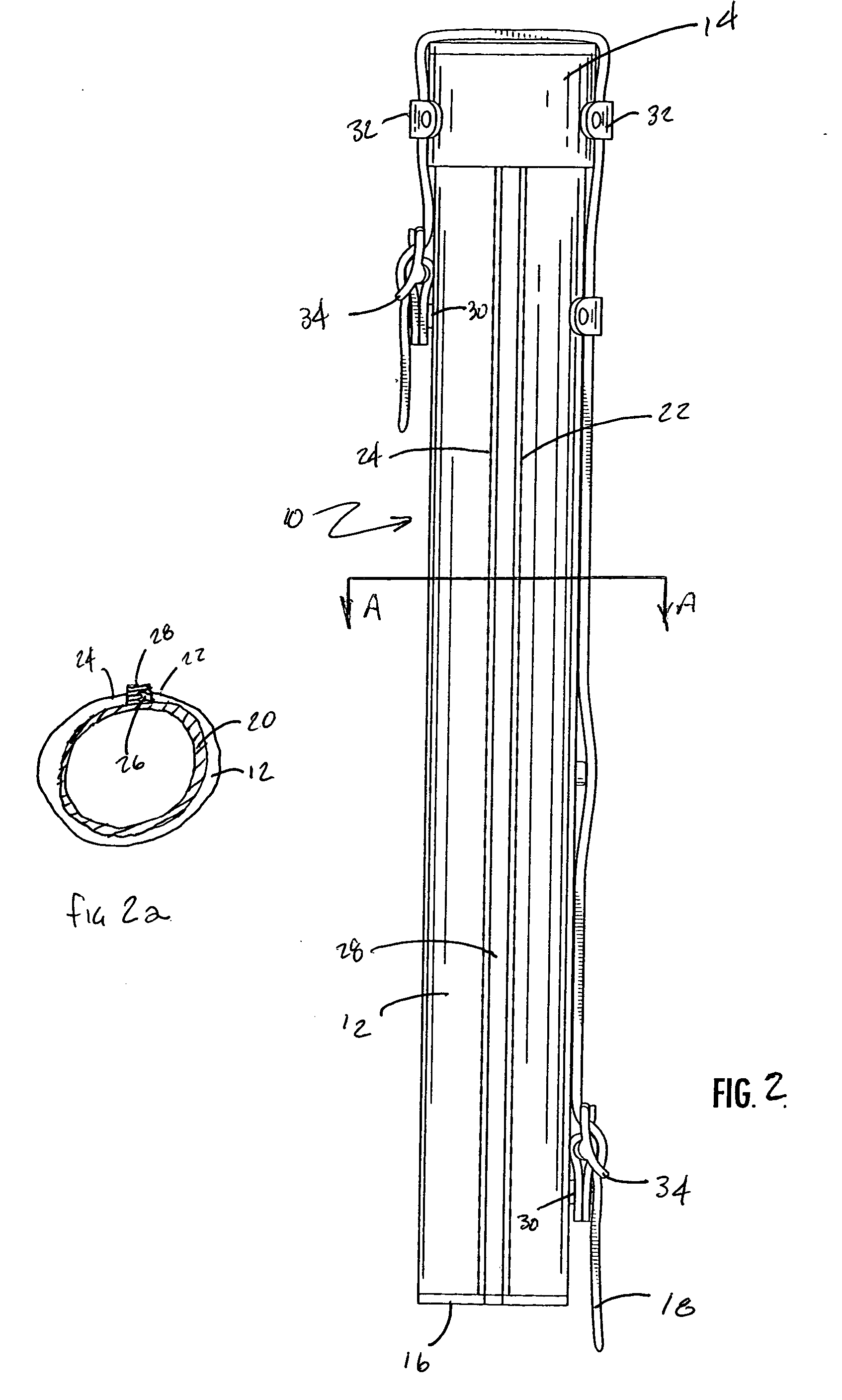
[0018] Now referring to the drawings, the tubular storage assembly is shown and generally illustrated in the figures. As can be seen the assembly 10 principally includes an outer shell member 12, top and bottom end caps 14, 16 and a transport handle 18. As will be further described below, the storage assembly 10 may also include an inner support tube 20 that provides additional ridgity to the assembly 10 while also providing a smooth inner surface to facilitate insertion and removal of rolled drawings and such.

[0019] Turning to FIG. 1, the storage assembly 10 can be seen to be substantially tubular. While the assembly 10 is shown as a cylindrical tube, clearly any tubular configuration such as octagonal, hexagonal, square, etc would also fall within the disclosure of the present invention. The general concept is directed to providing a tubular storage assembly 10 and a method of making the same that utilizes a heavy weight outer shell material 12 and accordingly the exact shape of ...


PUM


Abstract

A tubular storage assembly and method of making the same is disclosed. The present invention provides a tubular storage assembly that has an outer shell of heavy weight material such as an un-cut leather hide. The outer shell material is formed into the desired shape having two opposite edges that are configured to mate in the finished assembly. A zipper or other suitable fastening system is stitched onto the opposite edges while the shell material is flat. The mating edges are drawn together and the fastening system engages to retain the shell in the tubular formation. Finally the fasteners are concealed by permanently adhering a cover strip over the fastening system. As can be seen in this manner the formation of a fully stitched tubular storage assembly is provided that overcomes the de-lamination problems often encountered in the prior art.

Description

CROSS-REFERENCE TO RELATED APPLICATIONS [0001] This application is related to and claims priority from earlier filed U.S. Provisional Patent Application No. 60 / 520,092, filed Nov. 14, 2003, the contents of which are incorporated herein by reference.BACKGROUND OF THE INVENTION [0002] The present invention relates generally to a new method of constructing a tubular assembly. More specifically, the present invention relates to a method of manufacturing and assembling a tubular storage assembly using heavy gauge cladding material, such as leather material from a full weight, un-cut hide. [0003] Typically, tubular storage assemblies are desirable for containing, protecting and transporting large format blueprints or artwork in a rolled fashion. As can be appreciated, this type of storage device is particularly desirable to architects, engineers, interior designers or artists who must frequently transport presentation materials to and from studios, clients' offices or project sites. In or...

Claims


Application Information

Patent Timeline
IPC IPC(8): A45C11/26A45C13/10A45C13/30B65D45/00
CPCA45C11/26A45C13/10A45C13/30B42P2241/20B42F7/02B42P2201/10A45C2005/037
Inventor MASSO, ROBIN
Owner MASSO ROBIN
Learn More