Torque sensitive sanitary diaphragm valves for use in the pharmaceutical industry and methods related thereto

a technology of sanitary diaphragm valve and pressure torque, which is applied in the direction of diaphragm valve, engine diaphragm, valve operating means/release devices, etc., can solve the problems of contaminating the products produced in subsequent batches, adding considerable cost, and chemicals in the flow area may get trapped between the middle of the stem and the stem's housing area, so as to facilitate the flow of solutions and increase the amount of torque required

Inactive Publication Date: 2005-05-19
MEYERS SCOTT CHRISTOPHER
View PDF12 Cites 10 Cited by
  • Summary
  • Abstract
  • Description
  • Claims
  • Application Information

AI Technical Summary

Benefits of technology

[0009]FIG. 1A. In this invention the housing contains a flow housing area (1) and a stem housing area (3). The flow housing area (1) is a location on a pipe, tubing, or other structure utilized to facilitate the flow of solutions between two areas where there is a desired to prevent the flow of the solutions. The stem housing area (3) is a hollow structure, such as a tube, with a first opening attached to the flow housing area and a second opening threaded for the stem. The stem (4) has a top, a middle, and a bottom. The top of the stem is attached to the slipping mechanism (5). The slipping mechanism (5) is attached to the handle (6). The middle of the stem is counter-threaded for the threaded stem housing's attachment area. The bottom of the stem is shaped to mate with the shape of the flow housing area. The diaphragm (2) is a flexible material that has a chemical contact side and a stem contact side. The diaphragm (2) is located in the first opening of the stem housing between the stem and the flow housing area.
[0010]FIG. 1B. Closing the valve is accomplished by rotation of the handle (6) causing the threaded and counter-threaded stem housing's stem attachment area and stem's stem housing attachment area respectively to move the stem (4) vertically down the stem housing area (3) until the bottom of the stem moves through the first opening of the stem housing into the flow housing area (1). During rotation of the handle, the stem (4) contacts the diaphragm (2) pushing the diaphragm's chemical contact side into the flow housing area (1) ultimately forming a seal with the surrounding flow housing area as the bottom of the stem mates with the flow housing area obstructing the flow of solutions. As diaphragm (2) compresses, the stem will begin to exert pressure on the handle requiring an increase the amount of torque necessary to continue rotating the handle. When a pre-set torque is exerted on the handle, the slipping mechanism (5) will allow the handle to rotate but will not allow the threaded stem housing and counter-threaded stem to further engage preventing the stem from apply additional pressure on the diaphragm.

Problems solved by technology

Improperly sanitizing equipment can result in contamination of the products produced in subsequent batches adding considerable cost.
Because in ordinary valves closing the valve causes the valve's stem to protrude into the flow area and opening the valve causes the stem to retract into the stem's housing area, often chemicals that are in the flow area may get trapped between the middle of the stem and the stem's housing area.
The trapped chemicals are often difficult to remove during a sanitizing process allowing the trapped chemicals to be reintroduced into the flow area when the valve is subsequently used.
One major problems of using diaphragms in current valves is that the diaphragm can warp and / or become irregular and may not seal properly when the operator manually closes the valve because the diaphragms are exposed to the extreme conditions of the steam sterilization procedure multiple times and because over exertion of pressure from the stem due to over rotating the handle.
Unfortunately, these measures have not provided to be a satisfactory solution because it is not easy to predict when diaphragm warping will occur and typically the problem is detected too late—generally after a biological contamination that resulted from a breach to the sterile barrier.
In addition, the success of diaphragm replacement can vary from operator to operator and therefore may require labor intensive leak testing and re-replacement in order to assure no leaks are present for a even new diaphragm.

Method used


Image

  • Torque sensitive sanitary diaphragm valves for use in the pharmaceutical industry and methods related thereto
  • Torque sensitive sanitary diaphragm valves for use in the pharmaceutical industry and methods related thereto
  • Torque sensitive sanitary diaphragm valves for use in the pharmaceutical industry and methods related thereto

Examples


Embodiment Construction

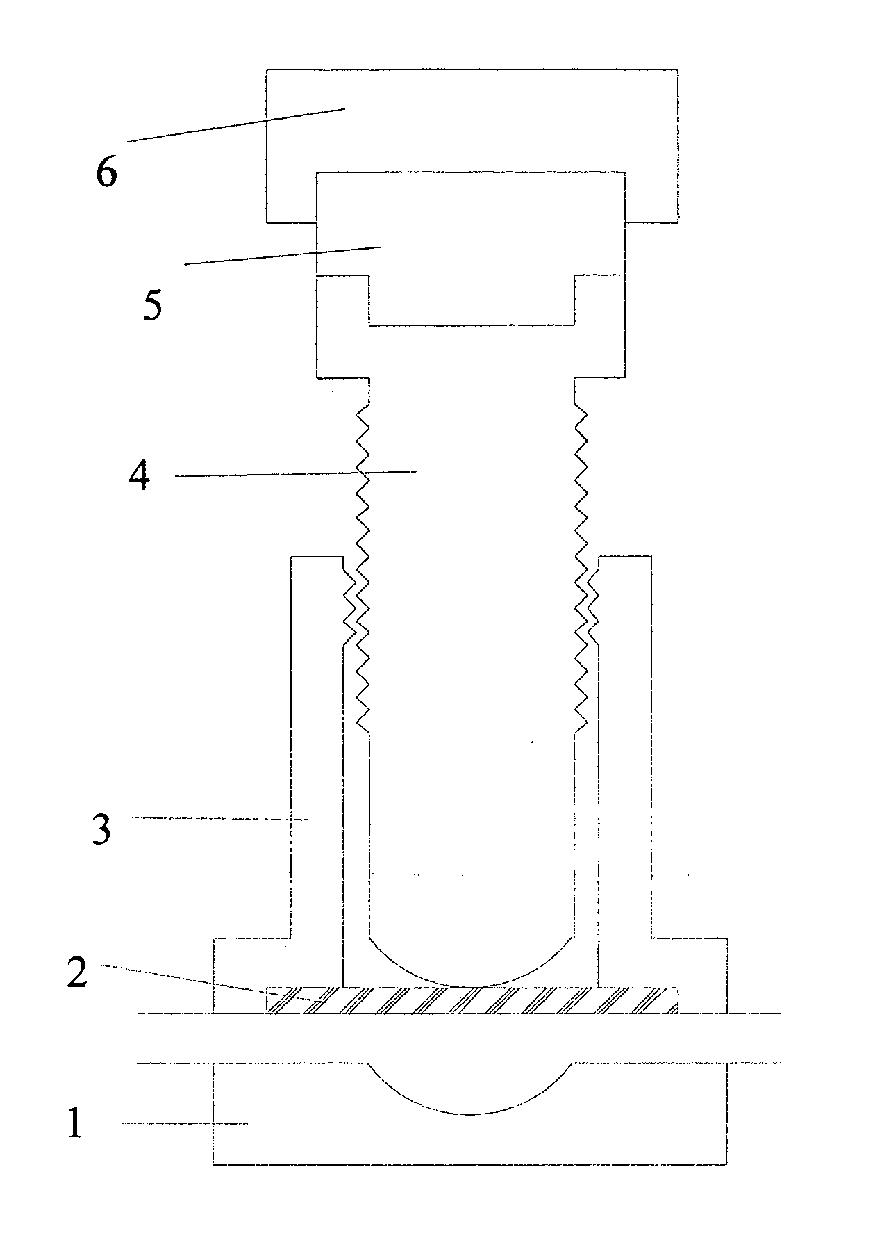
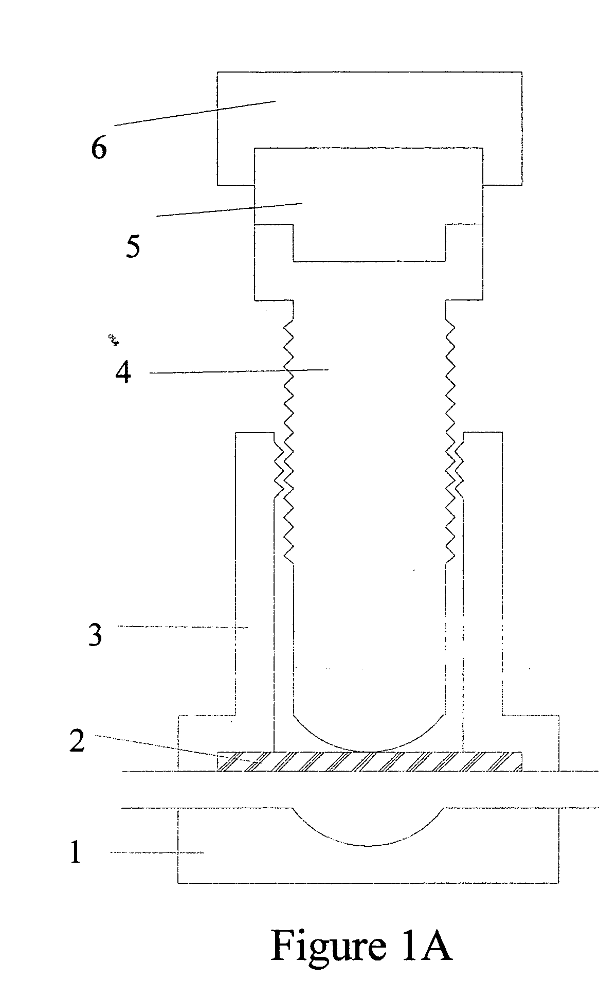
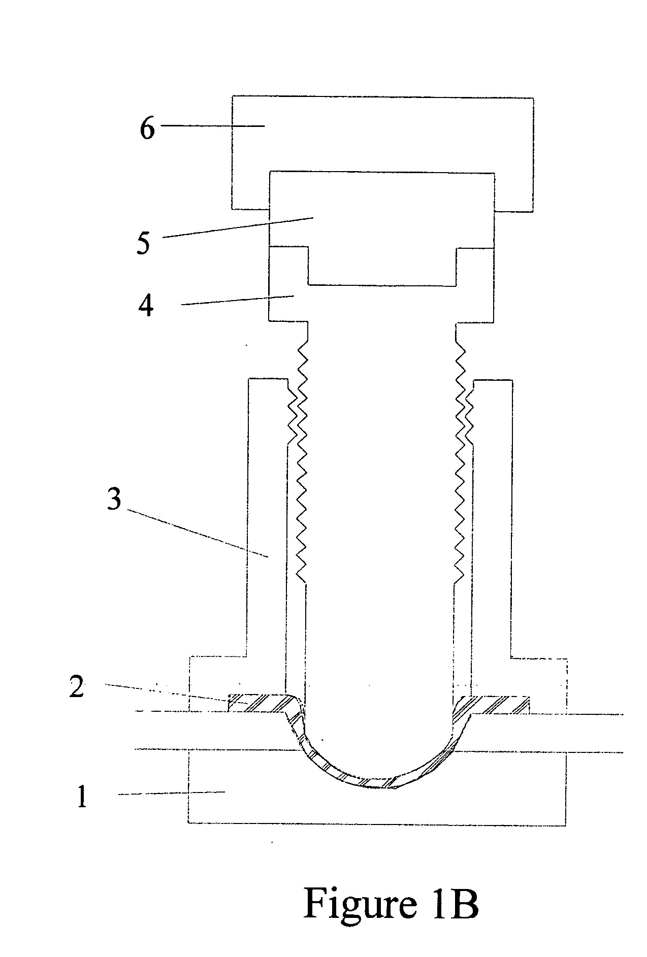
[0013] The critical feature sanitary diaphragm valve is the pressure obtain when mating the stem bottom, the diaphragm, and the flow area. If the valve diaphragm warps and a valve stem no longer provides proper sealing force when the operator places the valve in the fully closed position, then the valve will leak until it is disassembled and the diaphragm manually adjusted. By expanding the valve stem travel range of operation and modifying the valve handle to “slip” when a pre-set torque is reached, a reproducible seal pressure is achieved resulting in superior cost effective manufacturing capabilities.

[0014] Pressure sensitive sanitary diaphragm valves contain five major components: a housing, a stem, a handle, a diaphragm, and a slipping mechanism.

[0015] In one example of this invention the housing contains a flow housing area and a stem housing area. The flow housing area is a location on a pipe, tubing, or other structure utilized to facilitate the flow of solutions between t...


PUM


Abstract

This invention relates to pressure torque sanitary diaphragm valves and methods of using torque sensitive sanitary valves in the production of chemical and biological therapeutics to obtain procedural reproducibility in the production pharmaceutical compounds and intermediates related thereto.

Description

FIELD OF THE INVENTION [0001] This invention relates to pressure torque sanitary diaphragm valves and methods of using torque sensitive sanitary valves in the production of chemical and biological therapeutics to obtain procedural reproducibility in the production pharmaceutical compounds and intermediates related thereto. BACKGROUND OF THE INVENTION [0002] Pharmaceutical products are significant portion of the national economy, and the process used by pharmaceutical companies to produce these products are regulated by the Food and Drug Administration (FDA). The Division of Manufacturing and Product Quality requires Good Manufacturing Practice for the production of human use pharmaceuticals. The FDA regulates the production of pharmaceuticals to ensure that the methods utilized produce a pharmaceutical products are of high quality and provides Certificates of Pharmaceutical Products to firms that legally market drug products. [0003] The production of medicines requires the utilizati...

Claims


Application Information

Patent Timeline
Patent Type & Authority Applications(United States)
IPC IPC(8): F16K7/12F16K7/16F16K31/44F16K31/50
CPCF16K7/123F16K35/04F16K31/50F16K7/16
Inventor MEYERS, SCOTT CHRISTOPHER
Owner MEYERS SCOTT CHRISTOPHER
Why Eureka
Try Eureka